Cheap FM Radio Transmitter: Teardown
Hello all - it's been awhile since I last posted. Let's get to it.
Sitting on my desk for the past month is a small battery powered FM transmitter sold by Straight Talk, the cell phone carrier. The device is meant for older cars without Bluetooth - the driver can plug the transmitter into their phone and listen to music off of an empty FM station on the car radio, transmitting data from the phone to the radio. I got it at a local dollar store and haven't used it as much as I thought I would, so I'd like to present the innards of this device and explain the parts that I can. Hopefully you learn something new about electronics from this teardown.
I did another (more destructive) teardown of a different transmitter last year - you can find that here if you're interested.
An Overview
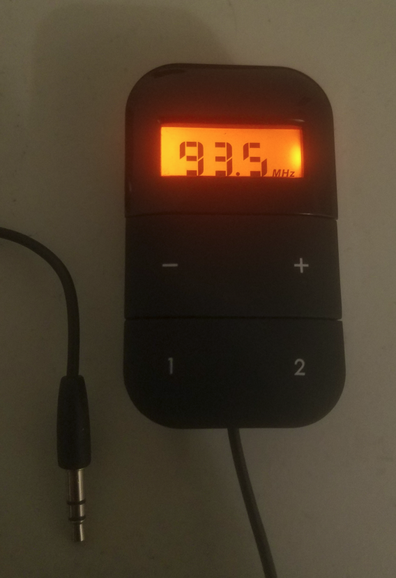
For $2, this device is pretty solidly built. The front of the transmitter is some sort of soft plastic, with a small push button on the top which turns the device on and off. When on, a LCD displays the frequency being used with an orange backlight.
A 3.5mm headphone jack can be inserted into a phone to broadcast audio over the frequency displayed on the screen. The +/- buttons allow the user to pick any channel in the USA FM band, and up to two frequencies can be saved and recalled using the 1/2 buttons.
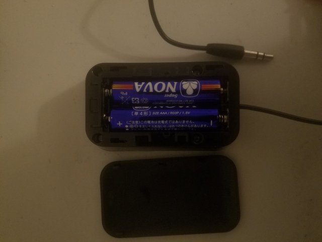
The back of the device has a sliding plate which can be easily removed to reveal two replaceable AAA batteries, which provide power to the transmitter. The transmitter actually included these batteries, which was nice.
At the risk of repeating myself, externally it's pretty decent for the $2 I paid. Doing some research online, I find that it is typically sold for closer to $10, which makes a lot more sense. This is then another case of the dollar store carrying surplus items that didn't sell well at other stores, which is why I was able to pick it up for so little.
Now, onto the interesting part.
Teardown
Underneath the batteries (which are easily removed) are four Philips head screws, which happily were not glued to the frame. It's refreshing to see a company that isn't actively preventing its customers from disassembling their products.
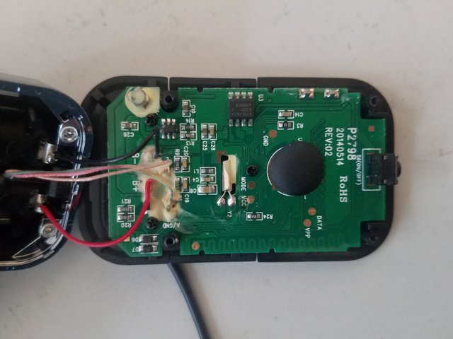
With the screws out, the main printed circuit board pops out. The board itself is still to the battery bracket by four wires (two audio, two power).
Immediately a disappointment is visible - the company hid some of their electronics under that black epoxy! This is something I see happen a lot in cheap calculators, and it's a shame. Perhaps there's a technical reason for hiding some of the board, but I assume it's to prevent reverse engineering. Thankfully, there are still some other parts to examine.
Three more small screws hold this board to the front plate containing the button covers and LCD. Embarrassingly, I was unable to remove two of the screws with my limited tools. Since I want to reassemble and possibly use this device after the teardown (a rarity), please forgive me for not breaking the board to see the other side. I was able to pull back the board a little bit to see that there isn't as much electrical stuff on that side, at least.
Back to the main board, to the right, we can see the on/off switch (labelled as such on the PCB screen). The small metal cylinder in the center of the board is likely a crystal resonator, used to generate a precise frequency signal for certain integrated circuits. Under that (stretching along the bottom of the board) is what appears to be the transmitter's antenna, tuned to the FM band. It appears to be a type of meander antenna, presumably fed with a signal at the exposed metal circle on the left end (although it could be a meander dipole, fed at the center). Here's a better view of this meander antenna:
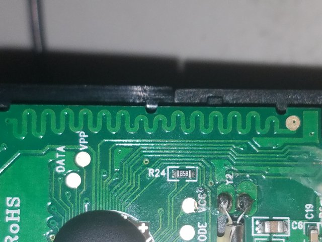
Definitely not an analytical design...
This antenna is where radio waves are radiated off of the circuit, and is likely linearly polarized (meaning that the net electric field of the wave points up or down the length of the antenna).
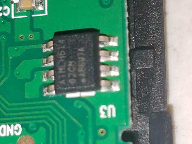
Next, let's take a look at the two integrated circuits not covered by the epoxy mask. The first, larger one superificially appears to be made by Atmel:
Annoyingly, the name printed on the IC doesn't return a datasheet or any indication of what this is. That being said, if I had to guess I'd say it was an EEPROM (Electrically Erasable Programmable Read-Only Memory) module, which uses transistors to store bits in memory. If true, this would be used to store saved channels on the device for easy recollection (which is what the 1 and 2 buttons on the front of the transmitter call up). Even if this isn't an EEPROM module, there still has to be some sort of memory onboard (maybe under the epoxy) in order to store these channels - but I'm actually fairly confident that this IC is the memory chip.
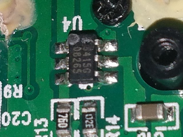
Another smaller IC is visible to the left of this mystery memory chip. Here is a closer view:
This label also returns no datasheet! Very frustrating, but it often happens when tearing down random electronics. Once again, we'll have to do our best to figure it out with what's around it. Assuming the other IC is the device's persistent memory, and the radio frequency generation happens under the epoxy, we can eliminate some options. Lithium battery charging integrated circuits can some in this package, but this transmitter is powered by disposable batteries.
If you look back at the overall picture of the board, you can see a small white blob to the upper left of the smaller IC. This is an inductor coil, and its presence (connected to the second mystery IC) makes me believe that the smaller integrated circuit shown above is most likely voltage booster or regulator. Here's an example of what I'm talking about, and in the same package too! Almost every voltage raising scheme uses an inductor due to their ability to generate a voltage when the current through them is changed. As such, this unidentified IC could be used to keep the transmitter on even at lower battery voltages, since the battery voltage will drop as the cells are drained. As before, we can't be sure what this small device does, but I think given the evidence a boost converter circuit seems most likely.
Conclusion
And that's about it for this device! I'm a little disappointed I can't see what's under the epoxied circle or know for sure what the two integrated circuits are, but hopefully you know a little bit more about how devices like this work. Not covered are the liquid crystal display and backlight (rather unremarkable devices on the back of the circuit board) and the buttons on the front of the transmitter. At least I was able to find the antenna this time ...
Thanks for reading!
All images used in this post are my own. You are welcome to use them with credit.
A cheap FM radio transmitter is an affordable tool for broadcasting your content over local FM frequencies. Ideal for small businesses, community events, or hobbyists, it allows easy setup without professional equipment. For artists or DJs, partnering with a music promotion company can amplify the reach of your broadcasts, ensuring your music reaches the right audience. Despite its low cost, these transmitters can deliver clear signals within a short range, making them perfect for localized marketing. Whether for promoting new tracks, hosting radio shows, or experimenting with sound, a cheap FM radio transmitter is a practical choice for cost-effective outreach.