ENGINE CLUTCHES
Hello dear steemians;
It's a good day today and I hope you're enjoying it. It's actually a special day for me because today's my birthday and I thought it'll be a good thing to drop this article today.
This topic is a very interesting one provided you follow attentively. By the end of this article you won't have to get to a technician before handling any problem related to an engine clutch.
But first we have to know all we need to know about the engine clutch.
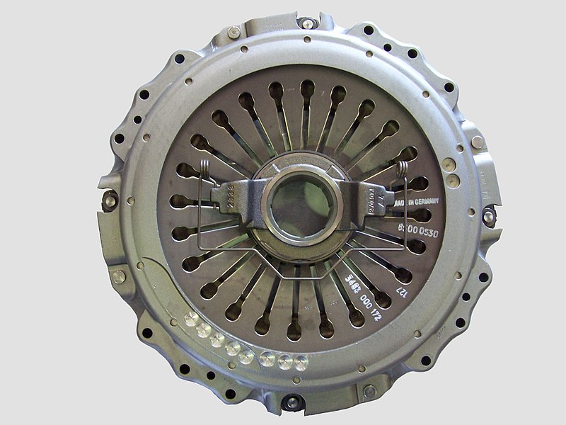
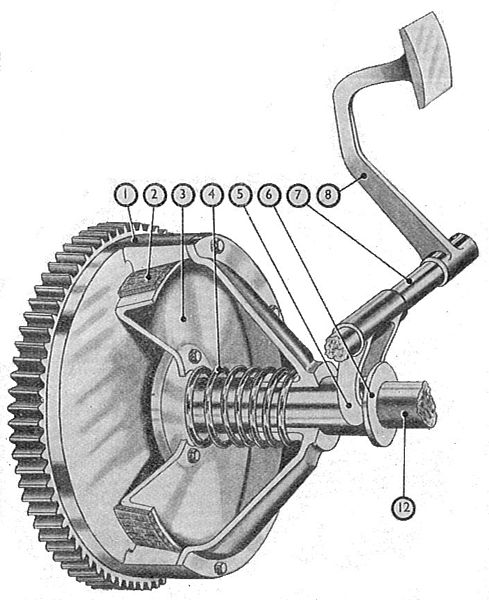
PULL TYPE CLUTCH from Wikimedia under GNU Free Documentation License
Definition/Purpose of a clutch:
A clutch is a mechanism designed to connect or disconnect the engine and transmission by operating a foot pedal. There are many types of clutches. All accomplish the same general purpose. A clutch is used to transmit engine power to the transmission in a manner that will allow the car to start in a smooth fashion. The clutch is also used to facilitate the shifting of transmission gears (gear box).
All automotive clutches used with standard transmissions are very similar in construction and operation. There are some differences in the details of the linkages as well as in the pressure-plate assemblies.
Clutches are classified based on their linkages and the number of pressure plates.
When classified based on their linkages, then we have:
- The Coil-pressure-spring type
- The Friction-disc type
- The Diaphragm-spring type.
- The semi-centrifugal type.
1. COIL-PRESSURE-SPRING TYPE:
The clutches of this type contains three to nine coil springs. The purpose of the coil springs is to spring-load the friction disc between the pressure plate and the engine flywheel in the coupling position. In this position, the friction between flywheel and the friction disc, and between the pressure plate and friction disc, causes the friction disc to rotate with the flywheel and pressure plate. The hub of the friction disc is splined to the clutch shaft. The shaft must thus rotate with the friction disc.
2. FRICTION-DISC TYPE:
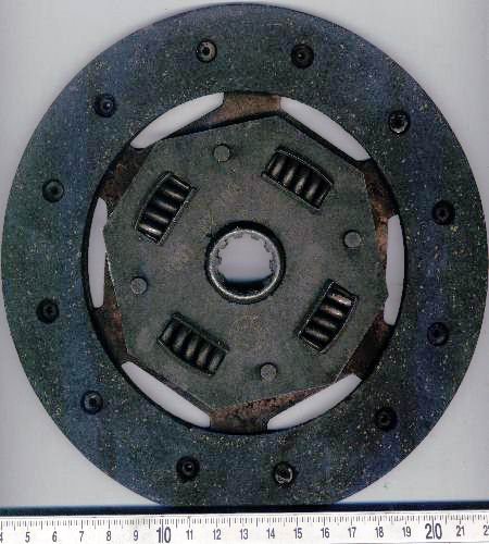
The friction-disc consists of a hub and plate assembly to which is attached a series of facings. The disc usually includes a cushioning device as well as a dampening device.
The cushioning device consists of waved cushion springs to which the friction facings are attached. The waves compress slightly as the clutch engages to provide the cushioning effect. The dampening device uses a series of heavy coil springs placed between the drive washers and riveted to the cushion springs and the hub flange.
The disc hub is thus driven through the springs, and they absorb a certain amount of torsional vibration. Stop pins limit the relative motion between the hub flange and the drive washers.
3. DIAPHRAGM-SPRING Clutch:
There are two variations of this design;
(a) Tapering-finger type
(b) Crown-pressure-spring type
Although they are different in construction, but both are similar in action.
(a) The Tapering-Finger Type: It has a one-piece diaphragm that is a solid ring on the outer diameter, with a series of tapering fingers pointing inward toward the clutch. When the throw-out bearing moves in against the ends of the fingers, the entire diaphragm is forced against a pivot ring, causing the diaphragm to dish inward. Thus, raising the pressure plate from the friction disc.
(b) The Crown-Pressure Spring Type: It is a variation of the diaphragm-spring clutch. The diaphragm spring is formed of a single corrugated plate of spring metal. The action is similar to that of the diaphragm-spring clutch; the movement of the throw-out bearing against the central section of the diaphragm causes it to flex so that the outer circumference lifts the pressure plate away from the friction disc and the flywheel, thus relieving the pressure and disengaging the clutch.
4. SEMI-CENTRIFUGAL CLUTCH:
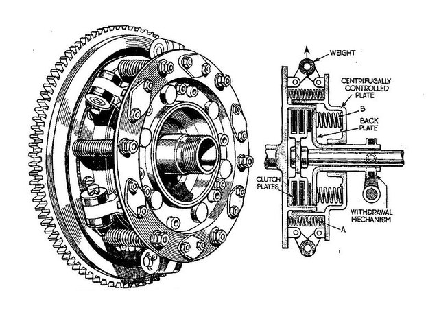
The semi-centrifugal clutch release levers have weights placed at their outer ends. The weights are so related to the release levers that as speed increases, centrifugal force on the weights causes the release levers to exert added pressure on the pressure plate. When the clutch is not rotating and is engaged, the only pressure on the pressure plate is produced by the springs. However, the higher the speed, the greater the pressure.
When classified based on the number of plates we have;
- Single-Plate Clutch
- Multi-plate Clutch
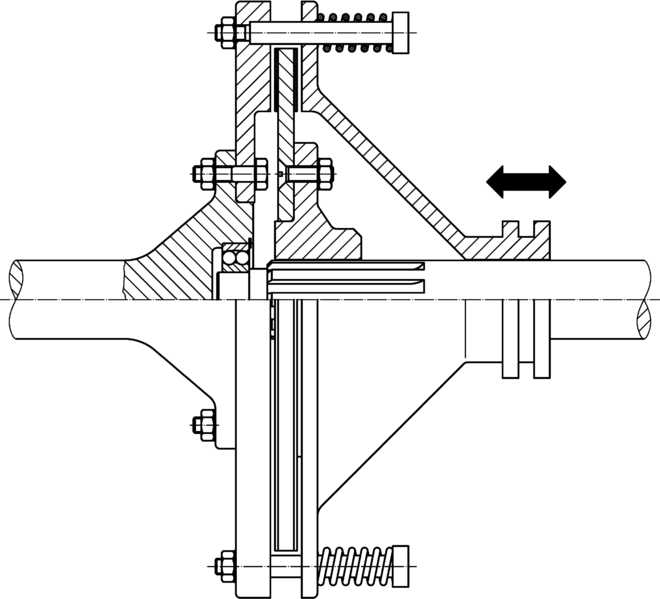
SINGLE-PLATE CLUTCH from Wikimedia under CCO License
This design of clutch for standard transmissions consists of four main parts;
1. The rear face of the flywheel which is the driving member.
2. The clutch plate: This is also referred to as the clutch disc or friction disc which is the driven member.
3. The pressure plate assembly: This is bolted to the flywheel which holds the clutch plate between its pressure plate face and the flywheel face. It is also a driving member.
4. The operating mechanism: This allows the driver to disengage and engage the clutch.
The clutch is a single dry plate unit of diaphragm spring type. The main components are driven plate, pressure plate assembly and release bearing.
The driven plate consists of a steel disc attached to a hub which slides on the splined clutch shaft. The friction linings are riveted to both sides of the disc.
The pressure plate assembly consists of the pressure plate, diaphragm spring and housing.
The release bearing is a ball bearing of special construction with an elongated outer ring that presses directly against the diaphragm spring when the clutch pedal is operated. The bearing is mounted on a guide sleeve in the gear box bell housing.
On hydraulic installations, the clutch pedal actuates a master cylinder where pressure on the fluid is generated, this pressure being transmitted through a hose to a slave cylinder mounted on the gear box case. Slave cylinder action is transmitted to the release bearing by a clutch lever pivoted on the transmission case.
.jpg)
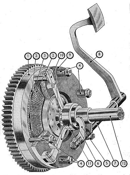
MULTI-PLATE CLUTCH from Wikimedia under CCO License
Multiplate clutch consists of a number of clutch plates, instead of only one clutch plate as in the case of single plate clutch. As the number of clutch plates are increased, the friction surface also increase. The increased number of friction surfaces obviously increases the capacity of the clutch to transmit torque. The plates are alternately fitted to the engine shaft and the gear box shaft. They are firmly pressed by strong coil spring and assembled in a drum. Each of the alternate plate slides in grooves on the flywheel and the other slides on splines on the pressure plate. Thus, each alternate plate has inner and outer splines.
Working Of Multi Plate Clutch
The multiple clutch works in the same way as the single plate clutch, by operating the clutch pedal. The multiplate clutches are used in heavy commercial vehicles, racing cars and motor cycles for transmitting high torque.
The multiple clutches may be dry or wet. When the clutch is operated in an oil bath, it is called a wet clutch. When the clutch is operated dry, it is called dry clutch. The wet clutch are generally used in conjunction with, or as a part of the automatic transmission.
Now to the practical aspect of the article;
Start by removing the gear box. Loosen the bolts holding the clutch assembly to the engine flywheel alternatively and evenly to avoid distortion, then lift off the clutch assembly. Slide the driven plate from the splined shaft, taking care not to get grease or oil on the friction linings.
Thoroughly clean all ports in a suitable solvent, with the exception of the driven plate friction linings and the release bearing. The release bearing must not be cleaned with solvent as this would wash the interior lubricant from the bearing.
The clutch cover, spring and the pressure plate assembly is an integral unit and must not be dismantled. If any part is defective the assembly must be renewed completely.
Inspect the surface of the flywheel where the driven plate makes contact. Small cracks on the surface are unimportant, but if there are any deep scratches, the flywheel should be machined smooth or renewed. Check the pressure plate for scoring or damage and that the operating surface is flat and true. Check the diaphragm springs for cracks and other damages and the release bearing for roughness when it is pressed and turned by the hand. Any parts which are worn or damaged must be removed.
Check the driven plate for loose rivets and broken or very loose torsional springs. The friction linings should be well proud of the rivet and have a light colour, with a polished glaze through which the grain of the material is very visible. A dark glazed deposit indicates oil on the facings and as this cannot be rectified, a new or relined plate will be required. Any sign of oil in the clutch will call for examination of the crankshaft main bearing oil seal.
Check the driven plate hub for a smooth sliding fit on the clutch shaft, removing any burrs on the shaft or in the hub.
Tightly fix the release bearing on the bearing sleeve. When it is pressed fully home, turn the bearing with the fingers to check for smooth operation. Apply multipurpose grease to the groove in the sleeve and to the withdrawal lever and ball pin. Install the release mechanism, fit in the return spring and press the dust cover.
The clutch assembly must be aligned with a special tool when it is fitted to the flywheel. Fit the special tool through the pressure plate and driven plate, then offer the assembly up to the flywheel locate dowels and enter the tool into the pilot bush in the flywheel. Fit the mounting bolts and tighten them alternatively and evenly to a torque 15 to 20 Nm. Refit the gear box and then adjust the clutch.
The pedal height should be correctly set according to the following instructions, particularly after any dismantling operation has been carried out on the clutch or operating mechanism. Correct adjustment of the release bearing clearance is essential.
Insufficient clearance will cause the release bearing to press on the diaphragm when the clutch is engaged, causing clutch slip and excessive bearing and driven plate wear.
Excessive clearance will prevent proper disengagement of the clutch, resulting in clutch drag and consequent difficulty in gear changing.
An occasional check should be made on the level of fluid in the master cylinder supply tank. Wipe dirt from around the cap before removing it. Top up the fluid if necessary to bring the level to the mark on the side of the tank. Use only the correct guide of fluid as recommended.
This operation is necessary to remove any air which may have entered the system due to the removal of components, or if the fluid level in the supply tank has been allowed to drop too low and air has entered through the fluid supply passage.
Fill the master cylinder supply tank with the correct grade of fluid. Remove the dust cap from the bleed screw on the slave cylinder, connect a length of rubber tube to the bleed screw and immerse the free end of the tube in a small quantity of the fluid in a clean glass jar. An assistant will be needed to operate the clutch pedal. Open the bleed screw about three quarters of a turn, then press the pedal firmly to the floor. Tighten the bleed screw while the pedal is held down, then allow the pedal to return slowly. Repeat this operation until the fluid flowing into the jar is completely free of air bubbles. Replenish the fluid in the supply tank frequently during this operation. If the level drops too low, air will be drawn into the system and the procedure will have to be started again.
On completion, top up the fluid to the correct level. It is not advisable to re-use fluid drained from the system.
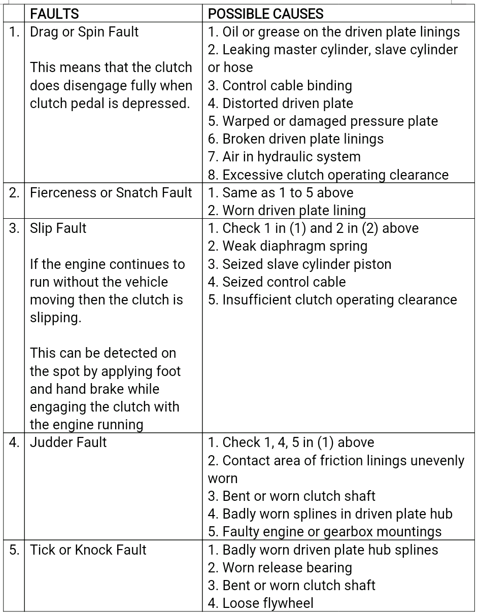
Table image created by me.
Sources:
Auto Technology Fundamentals by Dr K.A Salami
Images Links.
If you write STEM (Science, Technology, Engineering and Mathematics) related posts, consider joining #steemSTEM on steemit chat or discord here. If you are from Nigeria, you may want to include the #stemng tag in your post. You can visit this blog by @stemng for more details.
You can also join the ADSactly Discord here
.jpg)
.jpg)

Welcome to Steemit and to STEM community!
It's nice to see good engineering post.
I promoted it on Discord, at JDMLifestyle :D
Thanks man. I'm honored.
Nice work, well presented! Glad to see you here with us at steemit and steemstem!
Thanks man.
The clutch is a very powerful device in an automobile used to engage and disengage the gears.. Wonderful article.
Thanks brother.
A lot of people only know about the friction clutch that is found in the automobile. Thanks, to you, we are aware of the other types. Nicely written article sir.
Thanks Man.
This is an awesome post for someone of your reputation, no insult meant. Well done and please endeavour to engage other authours in their comment sections by reading and making meaningful contributions to their posts.
Noted. Thanks for the advice. I'll work on that aspect.
Happy birthday fam!
I must admit that you made it look like I don't know what a clutch was earlier. So clear and educative. I applaud your effort.
Clutch remain an important machine member in the automobile setup.
Keep steeming.
Thanks man.
Gosh so much information about the clutch. It's a good starting point for wanna be mechanics.
The clutch has to be one of the smartest design in our cars. Thanks for all the good research.
Thanks man. I'm honored.
H-max, you deserve a maximum round of applause for this nicely written article.
Keep up the good work.
Thanks bro.
Congratulations @h-max! You have completed some achievement on Steemit and have been rewarded with new badge(s) :
Click on any badge to view your own Board of Honor on SteemitBoard.
To support your work, I also upvoted your post!
For more information about SteemitBoard, click here
If you no longer want to receive notifications, reply to this comment with the word
STOPMost of these clutch types are either extinct or are only used in much smaller factions of the automotive sector.
Kudos for a well composed post.