Building a digital thermometer using Lm35 and pic18f2580 microcontroller.
Hello steemians! how has your day been? Have you ever wanted to be able to tell the exact temperature of a place. Are you a snail farmer like me that it is required of you to always monitor the temperature of your snail farm?
Worry no more, for we are going to be building our our own digital thermometer.
Components Needed.
For this to come into light, we are going to be using the following components :
- LM 35 temperature sensor.
- Liquid Crystal Display (LCD).
- Variable resistor.
- Pic18f2580 microcontroller.
- For our power supply, we will be using a 9volt battery.
Brief description of components needed.
Variable Resistor
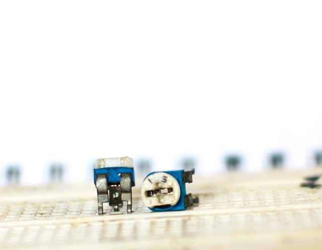
A resistor is an electrical component used to vary the flow of current. The larger the resistance, the slower the flow of current, and the lower the resistance, the faster the flow of current. A variable resistor is a type of resistor with a variable resistance. They come in various shapes and sizes. For this project, we are going to be using 5k ohm resistor. It has three pins; one of the pins is the ground pin, the second pin is the supply voltage pin and third pin is the output pin. It is usually connected to the device which we desire to vary the supplied voltage. The function of the variable resistor in our circuit, is to vary the contrast of our LCD. The variable resistor doesn't have polarity.
LM 35 Temperature Sensor.
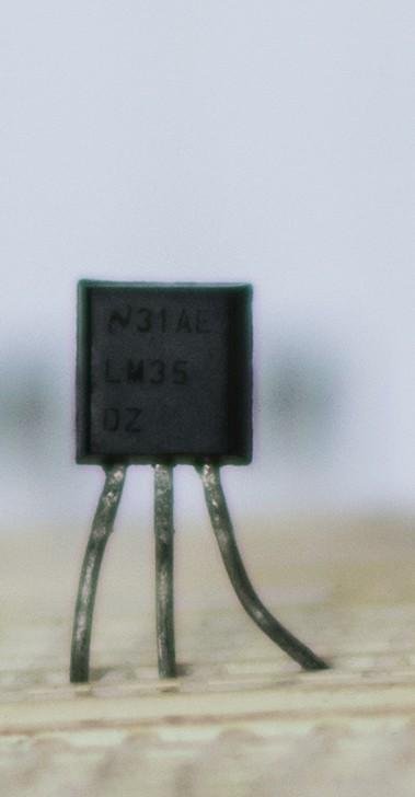
LM 35 temperature sensor developed by Texas instruments, it is an integrated precision sensor, with 0.5-25 degree Celsius. It has an output signal that is linearly proportional to the Celsius scale. It's output changes 10mV by degree Celsius; that is, at a temperature of 20°c, it will give an output of 200mV, at 0°c, it will give an output of 0mV and at 40°c, it will give an output of 400mV. It is calibrated directly in degree Celsius and hence does not require an external calibration. It has the ability to measure temperature from -52°c to +150°c. It operates with 4V to about 30v. It also has an accuracy of about 0.5°c to about 25°c. The function of the LM35 is to measure temperature of the environment.
LCD
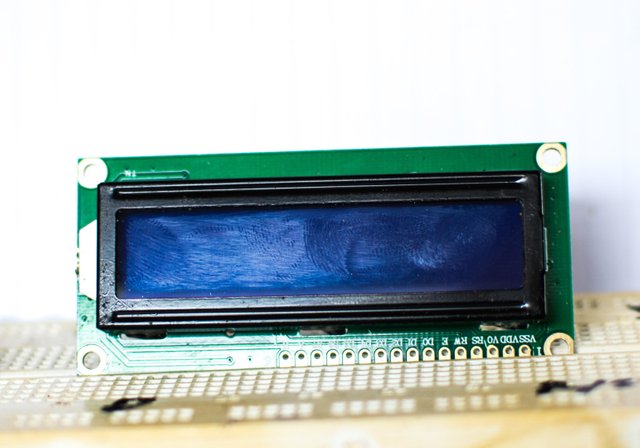
The acronym "LCD" stands for liquid crystal display. They are used in electrical and electronics engineering projects, when it is required to output a graphical display or an alphanumeric. They come in various shapes and sizes. An example is the 16×2, 40×2 etc. A 16×2 LCD means that it can display 16 characters in 2 lines, while a 40×2 LCD can display 40 characters in 2 lines. In terms of interfacing LCDs with microcontrollers, LCDs can be grouped into two categories : 1. The parallel Display LCDs. 2. The serial Display LCDs. The parallel display LCDs are more cheaper when compared to the serial display LCD. However, the serial display LCDs are more easier to use and saves more pins of the microcontroller. They are connected to the microcontroller using a single data line. For this project, we are going to be using a parallel display LCDs (lm016). It has 14 pins and a back light feature. Pin 1 is the Vss pin or you can call it the ground pin. We are going to connect it to the negative terminal of our power supply. Pin 2 is the VDD pin also know as the voltage supply pin. We are going to be connecting it to a +5v supply. Pin 3 is the contrast pin. It is used to vary the contrast of the LCD. Pin 4 is the register select pin. Pin 5 is the read and write pin of the LCD. The logic value on this pin determines if we will be able to read from the LCD or write to it. Pin 6 is the enable pin by which we have access to the LCD. Pin7- 14 are data pins. LCDs can be contacted as 8bit or 4bit. The function of the LCD in our circuit is to display the temperature reading as measured by our LM35.
Microcontroller
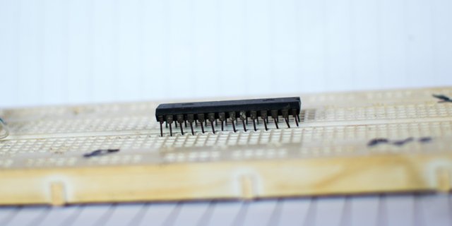
A Microcontroller is a small computer integrated on a single chip used in embedded system designs. They come in different shapes and sizes. They can perform various functions depending on the specifications of the manufacturer. Such functions include; analog to digital conversion, interrupts, timing, etc. Manufacturers of microcontrollers include; PIC, ATMEL etc. In embedded system design, the microcontroller unit is usually abrivated as MCU. In other for one to use a microcontroller, one must be able to use a programming language. Programming language are sets of instructions written and then converted to 1 and 0 by a compiler interact with the microcontroller. The most common languages used to program microcontrollers are C-language and Assembly language. I speak a little of Assembly, but my mother tongue is C. The microcontroller is the brain of every embedded system designFor our project, we are going to be using pic18f2580.
Brief Features of the PIC18f2580
The PIC18f2580 microcontroller has a flash memory and a memory size of 32Kb. A c.p.u speed (MIPS) of 10. It's also has a RAM size of 1,536 bytes. A 10 bit 8 channel and operating Voltage of 2v to 5.5v. It has a total number of 28pins. The function of the microcontroller in our circuits is to convert the analog signal from our LM35 to 1's and 0's and the display them on our LCD.Connection of the components
lm35
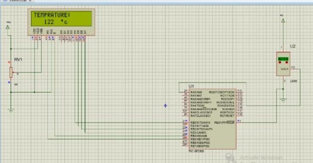
Pin 3 of our lm35 is taken to ground (negative terminal of our power supply). Pin 1 is the supply voltage pin and is connected to the positive terminal of our power supply unit. Pin 2 which is the output pin, is connected to the pin 2 of the microcontroller, which is the analog channel 0.LCD
Pin 1 and 5 are connected to ground. Pin 2 is connected to the positive terminal of our power supply. Pin 11, 12,13,14,6 and 4 are connected to pin 21,22,23,24,26 and 25 of the microcontroller respectively. Pin 3 is connected to the middle pin of our variable resistor.microcontroller
After making all the connections from our LCD and lm35 temperature sensor to the microcontroller, all we have to do is to connect the supply voltage pin to the (pin 20) to the positive terminal of our power supply and the ground pin (8 and 19) to ground. A microcontroller can sink and sources a maximum of 5volts therefore a voltage regulator should be attached to the supply voltage pin.Code for our circuit
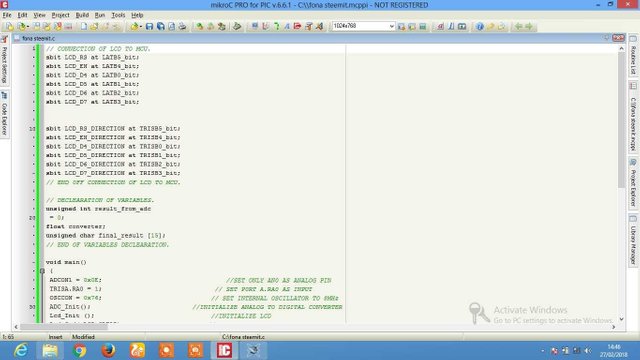
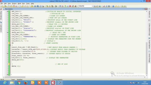
For our coding, we are going to be using the mikroC pro compiler. Firstly we are going to specify the connections and directions of our LCD to the MCU. Then we are going to declare our variables. A variable is a kind of housing to store data when coding. After that we are going to initialize the internal analog to digital converter (ADC) of our MCU. The next thing we are going to do is also to initialize our LCD, clear the screen, and turn off the cursor. When that is done we ate going to print out our steemit username. Mine is Fona so am going to print out Fona. After that is done we are going to printout digital thermometer, delay for 1500 milliseconds, which is equivalent to 1.5 seconds. The next thing to do is to clear the screen and display; " TEMPERATURE: and °c ". When that is done we are going to create a continuous loop in which the analog data from our lm35 will be converted to digital data and displayed on our LCD.
If you don't know how to code feel free to copy my code and any where you find difficult, feel free to use the comment section. All images where taken with a Nikon D5300 DSLR camera.
Below is a simulation of what our final circuit should look like.
CODE
// CONNECTION OF LCD TO MCU.
sbit LCD_RS at LATB5_bit;
sbit LCD_EN at LATB4_bit;
sbit LCD_D4 at LATB0_bit;
sbit LCD_D5 at LATB1_bit;
sbit LCD_D6 at LATB2_bit;
sbit LCD_D7 at LATB3_bit;
sbit LCD_RS_DIRECTION at TRISB5_bit;
sbit LCD_EN_DIRECTION at TRISB4_bit;
sbit LCD_D4_DIRECTION at TRISB0_bit;
sbit LCD_D5_DIRECTION at TRISB1_bit;
sbit LCD_D6_DIRECTION at TRISB2_bit;
sbit LCD_D7_DIRECTION at TRISB3_bit;
// END 0FF CONNECTION OF LCD TO MCU.
// DECLEARATION OF VARIABLES.
unsigned int result_from_adc
= 0;
float converter;
unsigned char final_result [15];
// END OF VARIABLES DECLEARATION.
void main()
{
ADCON1 = 0x0E; //SET ONLY AN0 AS ANALOG PIN
TRISA.RA0 = 1; // SET P0RT A.RA0 AS INPUT
OSCCON = 0x76; // SET INTERNAL OSCILLATOR TO 8MHz
ADC_Init(); //INITIALIZE ANALOG TO DIGITAL CONVERTER
Lcd_Init (); //INITIALIZE LCD
Lcd_Cmd(_LCD_CLEAR); //CLEAR LCD SCREEN
Lcd_Cmd(_LCD_CURSOR_OFF); //TURN OFF LCD CURSOR
Lcd_Out(1,1, "@fona"); //PRINTOUT @fona ON THE FIREST LINE
Lcd_Out(2,1, "steemit" ); //PRINTOUT steemit ON THE SECOND LINE
delay_ms(1500); //DELAY FOR 1.5 SECONDS
Lcd_Cmd(_LCD_CLEAR); //CLEAR LCD SCREEN
Lcd_Out(1,1, "digital"); //PRINTOUT digital ON FIRST LINE
Lcd_Out(2,1, "thermometer"); //PRINTOUT thermometer ON THE SECOND LINE
delay_ms(1000); // DELAY FOR 1 SEC
Lcd_Cmd(_LCD_CLEAR); // CLEAR LCD SCREEN
Lcd_Out(1,1, "TEMPRATURE:"); // PRINTOUT TEMPRATURE ON FIRST LINE
Lcd_chr(2,9,223); // DISPLAY THE CHARACTER CODE FOR DEGREE
Lcd_chr(2,10, 'c'); // DISPLAY C
do // START LOOPING
{
result_from_adc = ADC_Read(0); //GET RESULT FROM ANALOG CHANNEL 0
converter = result_from_adc*5000.0/1024.0;//CONVERT RESULT FROM CHANNEL0 TO VOLTAGE
converter = converter/10.0; // CONVERT FROM VOLTAGE TO CELCIUS
FloatToStr( converter, final_result); // CONVERT RESULT TO STRING
final_result [3] =0;
Lcd_Out(2,4, final_result); // DISPLAY THE TEMPRATURE
delay_ms(300);
} // END OF LOOP
while (1);
}
Reference.
More fame to you! I really enjoyed it. I think I could also get the parts if only I would have more time. I can't even solder my Solar Panel Cells I bought myself for Christmas :(
Thank you for the compliment. It's really nice knowing someone understands your article :)
You don't have enough reach yet, nothing is done in an instant, continue and you will grow. Keep an eye on your follower count and try to increase that by commenting on others articles. Like I am doing here. You help others that are talented and they will help others, and this is how whales are being born :)
Good article. It would be nice if you share your code instead of as image snapshots. :)
Alright I will do that
This is a great project to use with kids. I began to build stuff with my dad when I was about 11 yrs old.
You should also post over in the education sections!
Looking forward to seeing more of your posts.