Sound Operated Music Bell Circuit | Using UM66 IC and 555 Timer IC.
Assalamualaikum Everyone. I am @imranhassan From #Bangladesh
.png)
This circuit is made using a 555 timer IC and UM66 IC, capable of turning on and off the music bell, and it starts a music bell through a sound signal and turns off after a certain time.
| Components used and their functions |
|---|
UM66 IC:
 |
|---|
It is used to produce music or sound output. It is the main component used to play music in the circuit.
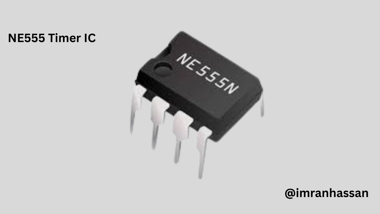
555 Timer IC:
 |
|---|
It is used for timing and signal control so that the circuit operates properly.
Resistors (R1, R2, R3) etc:
 |
|---|
These resistors are used for voltage division and signal control.
Capacitors (C1, C2, C3)etc:
 |
|---|
These capacitors help in holding the charge and managing the timing configuration.
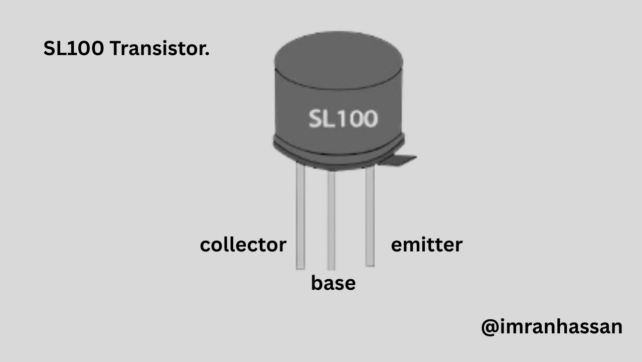
Transistor SL100:
 |
|---|
Transistor SL100 works to increase the signal strength of the circuit.
Transistor BC 548B:
 |
|---|
Transistor BC 548B helps to increase the output power, which is used to turn on the speaker or other output devices.
Diode (1N4001):
 |
|---|
Provides protection against reverse current in the circuit.
Variable Resistance:
 |
|---|
Used to adjust the input voltage of the circuit.
On/Off Switch:
 |
|---|
Used to turn the circuit on or off.
Microphone:
 |
|---|
Activates the circuit by collecting sound signals.
Buzzer:
 |
|---|
This alarm sounds as soon as the power is turned on.
Battery (3V to 5V):
 |
|---|
Used for power supply.
| Steps to make the circuit |
|---|
| Step 1: Connecting Triple Five (555) Timer IC and UM66 IC |
|---|
 |
|---|
First I drew the 555 timer IC and the UM66 IC. Then I marked the pinouts of the 555 timer IC correctly and connected them and added the UM66 IC to the circuit to produce music or sound output. These two ICs will perform the main function of the circuit; one will control the time and the other will play the music.
| Step 2: 555 IC Connection, UM66 IC Connection and Capacitor Connection |
|---|
 |
|---|
I connected pin numbers 1 and 5 of the 555 timer IC to ground. Then, I connected pins 8 and 4 to the positive line. After that, I connected a 220µF 10-volt capacitor to pin 5 of the 555 IC; it will help in the timing configuration of the circuit. Then, I connected pin 3 of the UM66 IC to ground. This IC will work to generate sound output from the circuit.
| Step 3: Resistance, Capacitor, Mic and Transistor Connection |
|---|
 |
|---|
I connected resistance 1 (10 kiloΩ), resistance 2 (470 kiloΩ) and resistance 3 (22 kiloΩ). Then I connected a C3 0.22 µF capacitor to pin 2. I connected a mic, which will collect a sound signal. Then I added a 0.1 µF capacitor, C2. After connecting the resistor 4 (150 kΩ), I connected the BC 548B transistor, which will increase the output power.
| Step 4: Connecting the variable resistance, capacitor and diode |
|---|
 |
|---|
Now, I connected a variable resistance to pin 6 and pin 7 and connected it to ground. Next, I connected the capacitor C1 (22 µF, 16 volts). Then, I connected a 1N4001 diode to pin 3 (output pin) of the 555 IC. This line went to pin 2 of the UM66 IC.
| Step 5: Connecting the UM66 IC, resistor, transistor and speaker |
|---|
 |
|---|
Then I connected a 100 Ω resistor to pin 1 (ground pin) of the UM66 IC. Next, I connected an SL100 transistor and an LS1 speaker. I added a 0.01 µF capacitor for filtering. Then I supplied a 3.7-volt positive line and added an on/off switch to control the circuit.
| Conclusion |
|---|
 |
|---|
It took me two days to make this circuit, and I had to work my brain a lot to make a post. Sometimes I feel bad for myself. While writing the parts installation texts. Then after finishing the entire post, I took a selfie with myself, and then in this diagram I confirmed the functionality of the circuit by adding other components, including resistors, capacitors, transistors and microphones. This is a simple, effective and cheap circuit that can be used in various fields.
.gif)
| Photography Details | 📱 Device: Walton Xanon90 | 📍 Location: Narayanganj, Bangladesh | 📷 Captured By: @imranhassan |
|---|
https://x.com/ImranHosen98536/status/1942994457810653354
Hello @imranhassan! 👋
Congratulations! This post has been upvoted through @steemcurator05. We support quality posts, good comments anywhere, and any tags.
Curated by: mohammadfaisal