Power ON Alarm with Auto OFF Circuit uses 555 ic.
Assalamualaikum Everyone. I am @imranhassan From #Bangladesh
.png) |
|---|
This can be a device that can be used in various places where a warning or sound is required as soon as the power is turned on. I have drawn this circuit myself and illustrated it beautifully step by step with coloured pens.
| Parts used and their functions |
|---|
555 Timer IC:
 |
|---|
Used for timing control and signal generation.
Resistor 47K, 47K, 100K:
 |
|---|
Used for voltage division, timing and signal control.
Diode 1N4007:
 |
|---|
Protects the circuit from reverse current.
Capacitor 0.1µF:
 |
|---|
Works in charge retention and timing configuration.
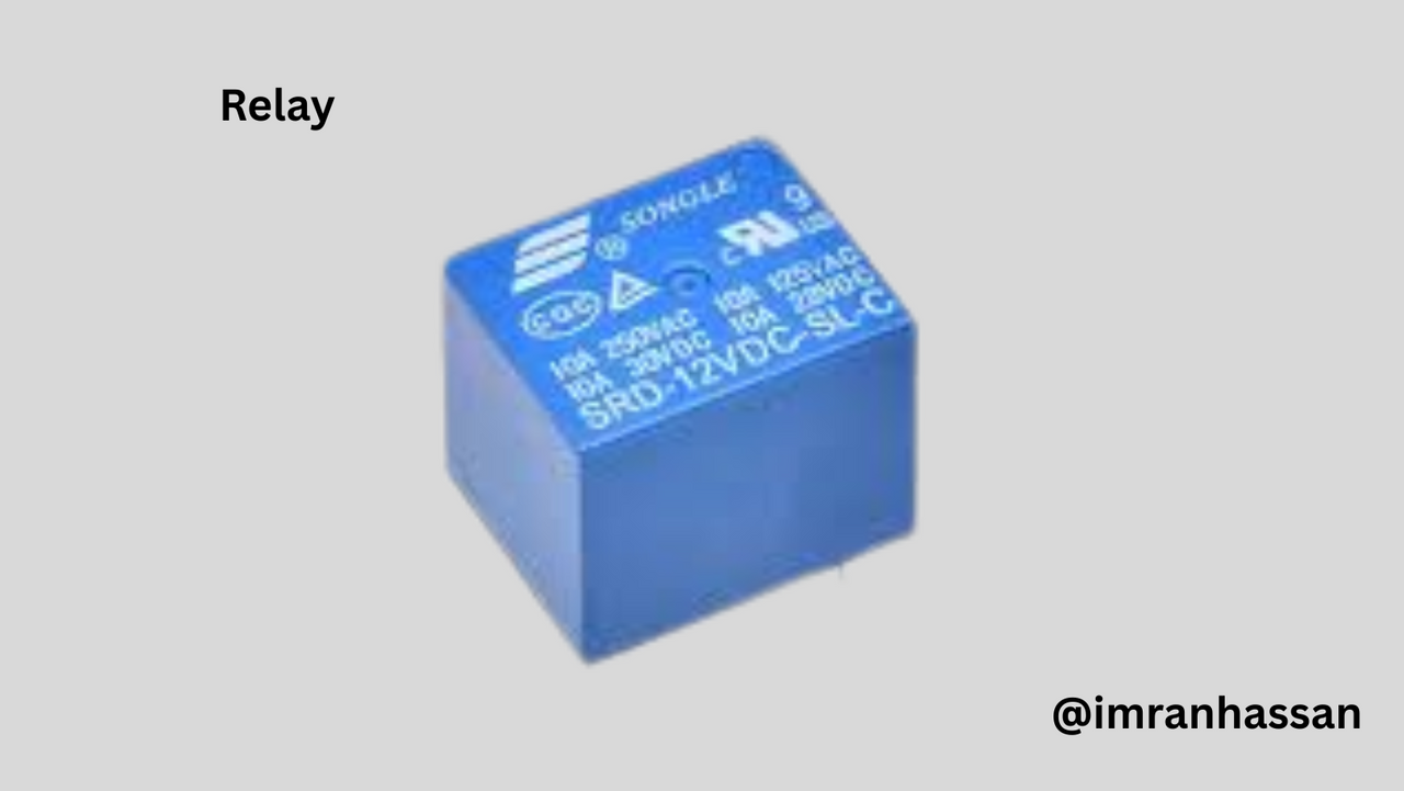
Relay:
 |
|---|
Used to turn on and off the alarm system.
Buzzer:
 |
|---|
Sounds as soon as the power is turned on.
Battery (5V to 15V):
 |
|---|
A 5V to 15V battery is used to supply power to the circuit.
| Step 1: Gathering the necessary equipment |
|---|
 |
|---|
I collected some necessary equipment before starting my drawing work. These included coloured pens (green, purple, white, orange, and blue), pencils, a scale, and an art page. With these materials, I drew the circuit diagram step by step.
| Step 2: 555 Timer IC Connection |
|---|
 |
|---|
In this step, I used a 555 timer IC. I connected pins 4 and 8 of the IC together and gave +3.7V to the 5V power line. Then, pin 1 of the IC is connected to the ground line. A capacitor is connected to pin 5, which will work in the timing configuration. The main timing and output control of the circuit will be done using this IC.
| Step 3: Resistor and Capacitor Connection |
|---|
 |
|---|
In this step, I have connected resistors R1 and R2 in the circuit, both of 47 kΩ rating, and resistor R3 is 100 kΩ. These resistors are connected for the timing control of the 555 timer IC. Capacitors C2 and C3 are connected in a 10 nanofarad timing configuration and help in generating the signal.
| Step 4: Relay and Alarm Connection |
|---|
 |
|---|
In this step, I have connected the output pin, pin 3 of the IC, to the relay and alarm. After the relay is activated, the alarm will start sounding, which can be heard immediately after power on. The alarm will automatically turn off after a certain time.
| Conclusion |
|---|
 |
|---|
I have made the entire project step by step by hand. Here a power-on alarm has been made using a 555 timer IC, which sounds a warning sound as soon as the power is turned on and automatically turns off after a certain time. In this circuit I have used resistors, capacitors, relays and other components which have made it functional and easily available.
.gif)
| Photography Details | 📱 Device: Walton Xanon90 | 📍 Location: Narayanganj, Bangladesh | 📷 Captured By: @imranhassan |
|---|
Thank you to the Curator 6 team for voting for my post.
Your support has encouraged me even more. I will try to create more educational and quality content in the future.
Best wishes and gratitude.