12V Automatic Water Level Controller Circuit | Using NE555 Timer IC.
Assalamualaikum Everyone. I am @imranhassan From #Bangladesh
.png)
This circuit is designed in such a way that the water pump is automatically turned on or off according to the water level in the water tank. It uses a simple relay, transistor and some sensing wires, which give signals according to the presence of water.
| Components used and their functions |
|---|
NE555 Timer IC:

This IC is the main controller of the circuit. It receives the signal from the sensor and gives the output according to the set time, through which the pump is turned on or off.
Transistor (BC546):

This is an NPN transistor, it initially amplifies the input signal of the sensing line and starts the relay switching process.
Transistor (2N2222)

This transistor can handle high current. It is used in the final amplification stage to drive the relay.
Relay (12V):
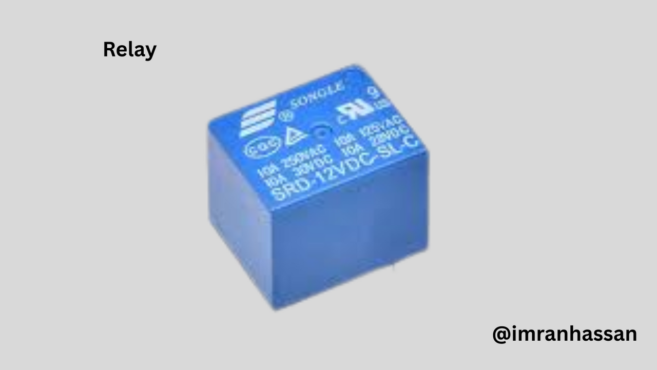
An electromechanical switch that turns the pump on or off based on the water level.
Resistor:

Keeps the transistor and LED safe by limiting the current.
Diode (1N4007):

Protects the circuit from the back EMF that is generated when the relay is off.
LED:

Used to indicate the water level—when the LED lights up, it means the relay/pump is on.
Capacitor (100uF):

Provides voltage filtering and stability in the circuit.
Sensing Wire:

These wires detect the water level and send a signal.
DC Power (12V):

Provides the power required to run the circuit.
| Step 1: Connecting NE555 Timer IC and Control Capacitor |
|---|
 |
|---|
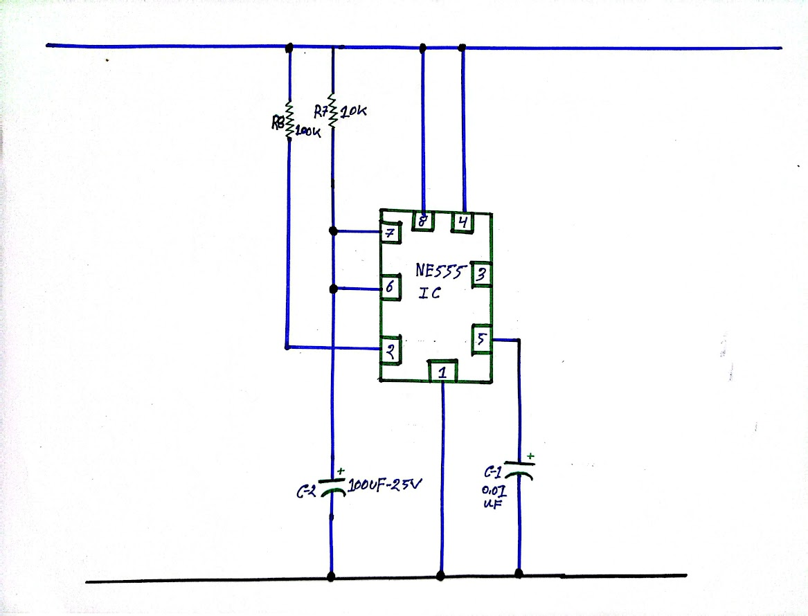
In this step, I have taken the NE555 Timer IC and marked each of its pin numbers. I then connected ground (GND) to pin 1 and positive 12V DC line to pin 8 and pin 4. Later, I connected 0.01μF capacitor (C1) to pin 5 which helps in stabilizing the control voltage.
| Step 2: Resistor and Capacitor Connection |
|---|
 |
|---|
In this step, I first connected pin 6 and pin 7 together. I placed a 10 kΩ resistor across this connection and a 100 mF capacitor downstream. Then I connected a 100 kΩ resistor to pin 2 which is used for timing and triggering of the circuit.
| Step 3: Input Signal Processing Connection |
|---|
 |
|---|
In this step, I drew three input lines which I connected to points A, B, and C. At the beginning of each line, I have connected a 2.2k ohm resistor, with which I have placed an LED (LED1, LED2, LED3) in series and these LEDs will give the water level signal when it drops to the very bottom and when it rises to the middle. Then I have connected an NPN transistor (BC546) with each LED, in whose base part a 100k ohm resistor is placed. Through this configuration, the signal coming from each input will act as a trigger separately and will reach the timer IC in the next step.
| Step 4: Relay and pump connection |
|---|
 |
|---|
In this step, I first connected the output pin-3 of the NE555 IC to the base of an NPN transistor BC546 with a 1k resistor. Then I drew a line from the previous input voltage section B and placed a 4.7k ohm resistor in the collector part of the transistor and connected it to the base of the transistor (2N2222).
Then I grounded the emitter part of the transistor and connected the relay to the collector part. I used a diode 1N4007 at the top of the relay, it protects the circuit from back current. I connected a DC pump to the output part of the relay which will be turned on and off through the relay. I also connected 10 kilohm and 220 ohm resistance to the power line of the circuit in this part, which controls the activation of the transistor.
| List of parts used |
|---|
| S.no | Component | Value | Qty |
|---|---|---|---|
| 1 | DC Power Supply | 12V | 1 |
| 2 | Timer IC | NE555 | 1 |
| 3 | NPN Transistor | BC546 | 4 |
| 4 | NPN Bipolar Transistor | PN2222 | 2 |
| 5 | LED | – | 3 |
| 6 | Resistors | 220Ω, 1K, 2.2K, 4.7K, 10K, 100K | 2, 1, 3, 1, 2, 4 |
| 7 | Electrolytic Capacitor | 100µF, 2.2µF | 1, 1 |
| 8 | Ceramic Capacitor | 0.01µF | 1 |
| 9 | Diode | 1N4007 | 1 |
| 10 | Relay | – | 1 |
| 11 | Motor – | 1 |
.gif)
| Photography Details | 📱 Device: Walton Xanon90 | 📍 Location: Narayanganj, Bangladesh | 📷 Captured By: @imranhassan |
|---|
https://x.com/ImranHosen98536/status/1944359746158440906