SLC21/WK2: Introduction to Basic Electrical Circuits & Cable Joint.
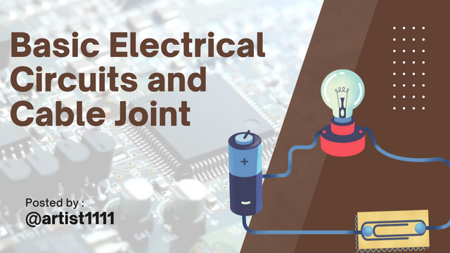
An electrical circuit is a pathway in which electric current travels through a network of interconnected electrical components.
A circuit includes a power source such as a battery or a power supply, conductors, or wires, and then the electrical devices including resistors, capacitors, and LEDs.
They are connected in a loop such that current can move from the power source to travel through other components and come back to the source in completing the circuit. Circuits can be as simple as a battery connected to a light bulb or as complex as those in modern computers.
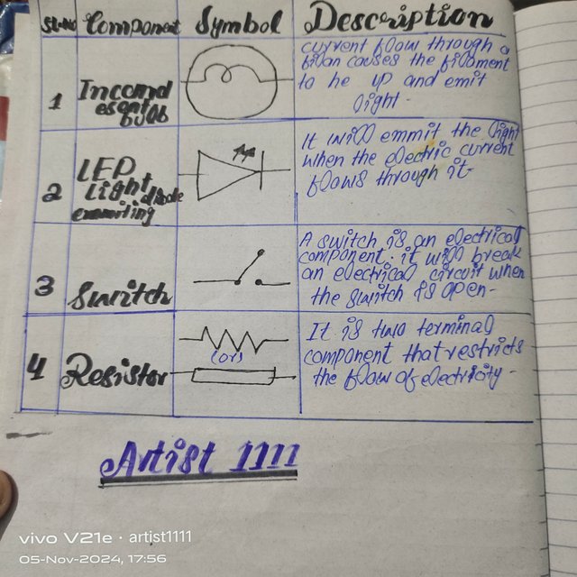 Basic components along description Basic components along description |
|---|
Importance of Electrical Circuits in Electrical Engineering
Electrical circuits are the backbone of all electrical and electronic devices. Their importance in electrical engineering lies in their fundamental role in powering and controlling devices and systems. Key reasons circuits are essential include:
Power Distribution: The circuits allow for controlled distribution of power to the devices for efficient and safe system operation. Household wiring as well as large industrial systems rely on circuits to receive power to each component.
Signal Processing: Communication systems apply circuits for the purpose of processing and transmitting signals with minimal distortion, hence technologies like smartphones, radios, and satellite systems work.
Automation and Control: Electrical circuits form the backbone of automation in industries, allowing for tight control over machinery, production lines, and robotics.
Design and Testing: Circuits are important to electrical engineers as they provide a means to design, test, and improve new technology. They form a basis for designing innovative systems such as renewable energy solutions, medical devices, and advanced electronics.
Safety and Reliability: The circuit designs ensure protection against overloads, short circuits, and other problems for the safe and reliable use in homes and industries.
- Conclusion
Electric circuits are of prime importance in transforming, controlling, and distributing power and signals, thus having an indispensable role in nearly every field of technology.
Differences Between Series Circuit and Parallel Circuit (Considering Resistor Circuits)
In electrical engineering, series and parallel circuits are two fundamental configurations used to connect components like resistors, each with unique properties that impact current, voltage, and resistance behavior.
| Property | Series Circuit | Parallel Circuit |
|---|---|---|
| Configuration | Resistors are connected end-to-end in a single path. | Resistors are connected with both ends to common points. |
| Current Flow | Same current flows through all resistors. | Current divides among branches, with each branch receiving a portion. |
| Voltage | Voltage across each resistor varies, adding up to the total voltage. | Voltage across each resistor is the same as the source voltage. |
| Total Resistance | Sum of individual resistances ( R_{total} = R_1 + R_2 + ... + R_n ) | Reciprocal of sum of reciprocals ( \frac{1}{R_{total}} = \frac{1}{R_1} + \frac{1}{R_2} + ... + \frac{1}{R_n} ) |
| Effect on Resistance | Total resistance increases with added resistors. | Total resistance decreases with added resistors. |
| Application | Used when the same current is needed through components. | Used when maintaining the same voltage across components is necessary. |
In summary, the choice between a series and parallel circuit depends on the desired behavior. Series circuits offer a single path for current and add up resistances, making them ideal for applications where the same current flow is required.
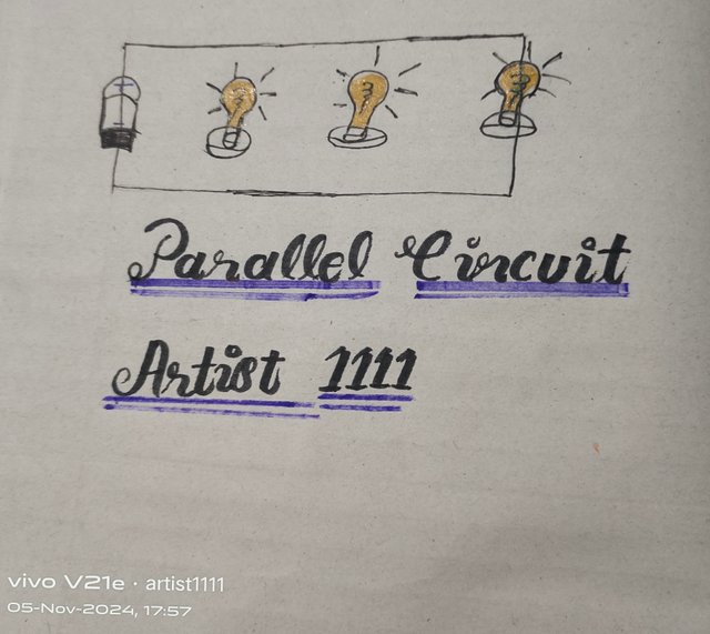
In contrast, parallel circuits split current among branches and keep voltage consistent across each resistor, making them suitable for systems needing constant voltage across multiple components.
Parallel circuit
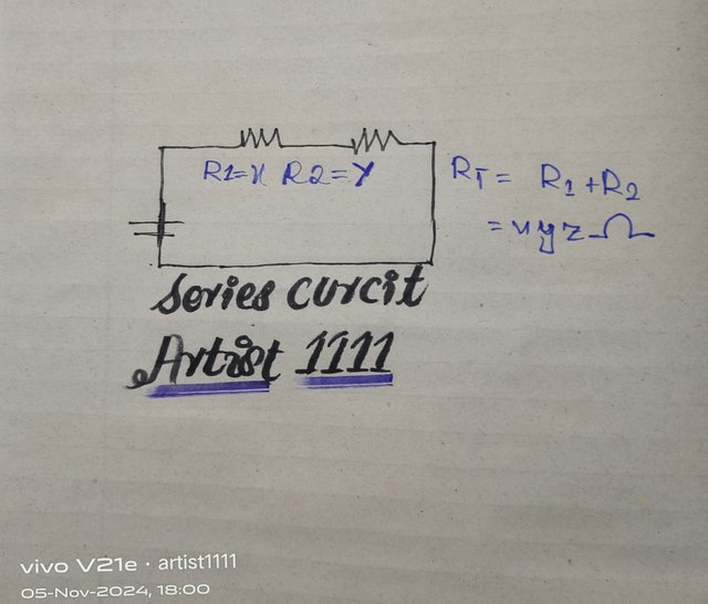
Series Circut
 |
|---|
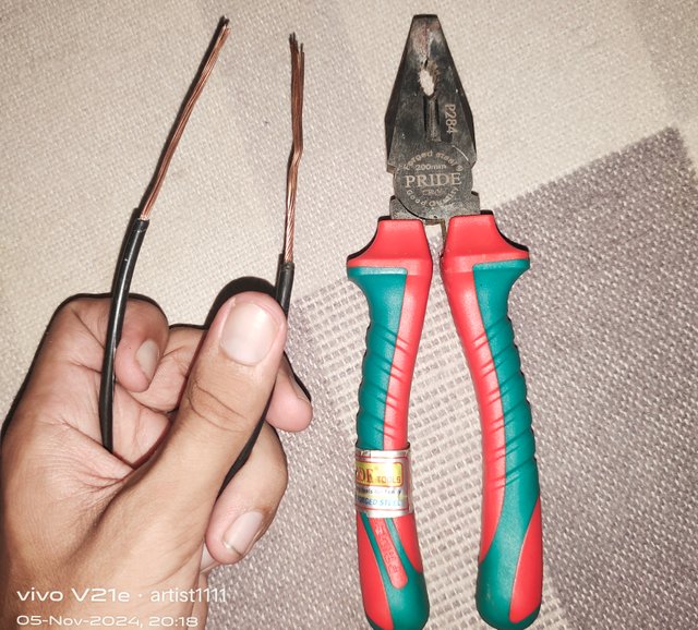
First, I removed the insulation from the ends of two pieces of wire, exposing the copper strands. I cleaned both ends to remove insulation, thus ensuring a secure and conductive connection.
 |
|---|
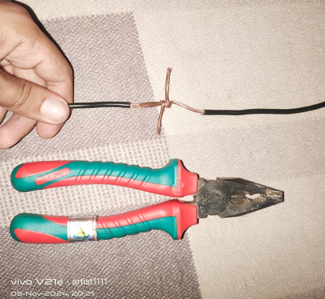
I overlapped the ends of the ends on one another, folding them in toward a 90° angle so that the copper wires came well into alignment with one another. I twisted the wires snugly in opposite directions, fixing them together; the installation should not loosen them thereafter.
 |
|---|
I used pliers to twist the connection tighter and then stop. In this way, the connection is tight and stable and usually reduces resistance and enhances conductivity, so that the joint is perfectly ready to use in reliable electrical applications.
At the end of this lesson, I would say that learning even small details about how to do electrical connections matters. Even stripping the insulation felt a bit like an exercise in patience, but it felt satisfying.
Then came the twisting part, which was surprisingly fun! Twisting wires in opposite directions felt like giving the wires a firm handshake, making sure they were connected and wouldn't easily come apart. It's like they became "best friends" in the process.
It was really nice to feel like a pro when tightening the joint with pliers. It reminded me a lot of being a craftsman, taking care of each wire in securing it to make it solid and safe.
It also made me realize that small details are important in electrical work. A well-made joint not only guarantees good conductivity but also keeps everything neat and tidy.
The end result did leave me more confident when handling wires and tools. Now, I finally understand why electricians take all that time; the right steps will get done.
Regards
artist1111
Point A you present quite well. Here we present the definition of electric circuit and the concept of current flow. In very simple terms, a circuit is a closed path with one or more paths for the flow of electricity. Current always returns from the positive end to the negative end and completes the current flow in the circuit. The importance of circuit in electrical engineering is clear.(1.4)
Most of you did well on point B. But I disagree with one of your conclusions. xyz refers to the results you have declared for the series circuit. But the circuit has two resistances which are x,y. So the total resistance of your series circuit will be x+y. If R1=x and R2=y then Rt= x+y. The difference in the circuit you mentioned is nicely presented. (3.2)
You have presented point C quite clearly. You have followed a series of instructions for the cable joint. Also you have presented the cable joint steps clearly. You didn't mention the scraping step. When you cut the insulation of the cable.(2.7)
Summarize what you learned at the end of the lesson. Here are your learning topics presented with pleasure. We are glad to have your sense of learning. (1.5)
Comment/Recommendation
We are glad for your great contribution. Stay tuned to enjoy the upcoming lessons with us. I wish you success in the competition. Love, from Team Electrical.
Dear friend, thank you for your analysis. However, I would say that mathematically, it's incorrect to state that X + Y = XY. We cannot express this case as multiplication rather than addition. As I mentioned, Rt = R1 + R2, which implies Rt = Rx + Ry.
In this context, when I referred to "xyz," I did not mean that X + Y = XYZ. Rather, I meant that the result could be any of "X," "Y," or "Z" depending on the values used.
Thank you for your insights!
Impressed by your deep knowledge of circuits! Such detailed and pictorial explanations make learning easier for beginners. Awesome work. Good luck for the contest.
Dear, Thank you very much for attending the second week of Basic Electricity Lesson. Submit your homework link in the comments section.