Ladder Diagram PLC Programming and Solar Power
Dear friends, today I am going to join the weekly learning challenge.Today's learning challenge is hosted by respected sir @mahadisalim and this is my first time joining this challenge. SLC22/WK5: Ladder Diagram PLC Programming and Solar Power. The challenge is a bit complicated, but I will try my best to organize everything nicely here.Since this is my first time joining, I think the chances of getting similar results are very low.
 |
|---|
I will start my work right now without further ado, so to that end, I will try to answer each question step by step and solve it neatly.
What is meant by ladder diagram PLC programming? Draw a ladder diagram and explain.
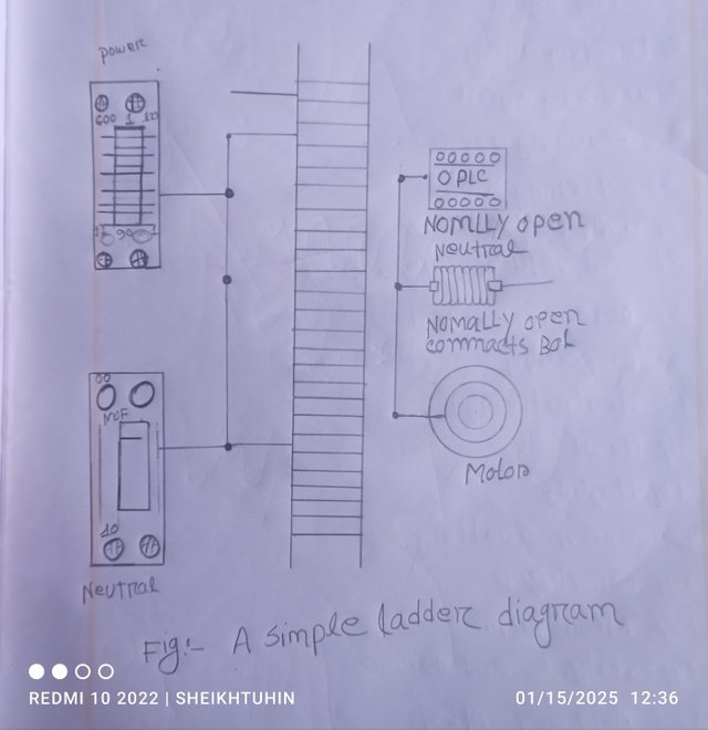
A ladder diagram is a graphical representation of the PLC programming language that shows the logical connections and actions of electrical relays. A ladder diagram looks a lot like a ladder. Where the two vertical lines indicate the power supply and the horizontal lines indicate the control logic.
I have drawn a ladder here:
 |
|---|
Explanation of the image:
Two parts of a vertical line:
Left line:
It supplies power and is indicated as a power conductor.
Contact:
Usually it is a switch that is automatically turned on when pressed and turned off when pressed again.
Motor:
Motors are usually used as output.When the contact switch is automatic, the motor starts and when the contact switch is closed, the motor stops due to lack of power supply.
Write the work by drawing the symbols of the input and output elements of the ladder diagram.
Symbolic drawing of input and output elements of a ladder diagram:
Input symbol:
Input symbols are typically used to enter data into a PLC.
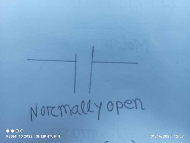
Normally open contact:
 |
|---|
This contact closes when the input signal is activated.When this contact is closed, the circuit is complete.
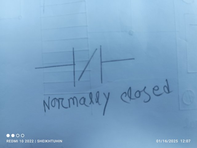
Normally closed contract:
 |
|---|
When the input signal is activated, this contact automatically opens and the connection is disconnected.
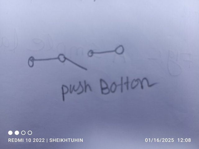
Push button:
 |
|---|
It represents a push button that, when pushed, automates the circuit and starts the supply.
There are also some input symbols, including limit switches, which are notable.
Output symbol:
Output symbols are used to output information from the PLC.Usually output symbols control other things, including motors.
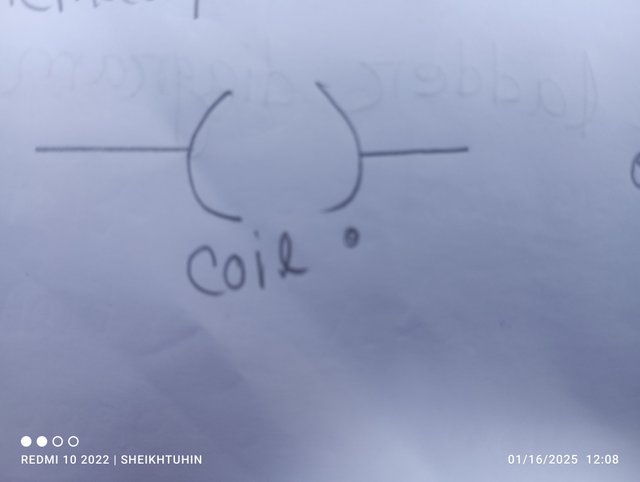
Coil:
 |
|---|
A coil represents an output that, when activated, turns a device on or off.
There are several other components, including power rails, that are identified as output symbols.
Draw the ladder diagram with three input ladder logic gates (AND, OR) and explain with practicals.
[With symbols and truth tables]
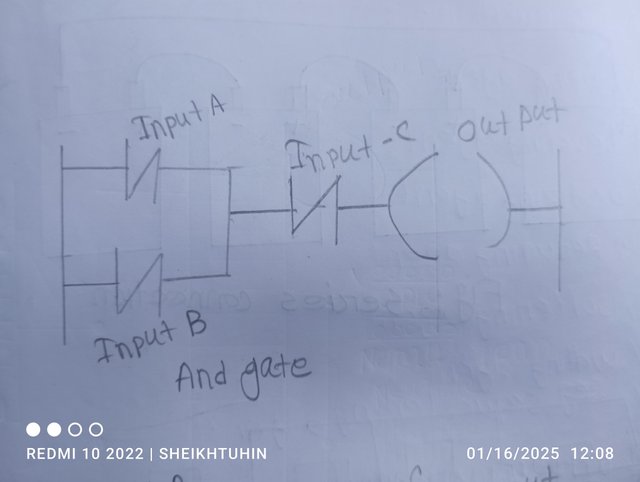
AND gate:
The AND gate has multiple inputs and one output.
The ladder diagram of a three-input AND gate is drawn below:
 |
|---|
In the figure, three inputs are connected to the AND gate.When all three inputs are 1, the output coil is activated.
OR Gate:
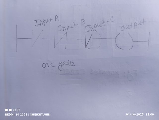
An OR gate also has multiple inputs and one output. When any one of the inputs is active, the output coil is activated.Below is a diagram of an OR gate:
 |
|---|
The figure shows three input OR gates connected. When any one of them is 1, the output coil is activated.
Truth table:
| Input A | Input B | Input C | AND output | OR output |
|---|---|---|---|---|
| 0 | 0 | 0 | 0 | 0 |
| 0 | 0 | 1 | 0 | 1 |
| 0 | 1 | 0 | 0 | 1 |
| 0 | 1 | 1 | 0 | 1 |
| 1 | 0 | 0 | 0 | 1 |
| 1 | 0 | 1 | 0 | 1 |
| 1 | 1 | 0 | 0 | 1 |
| 1 | 1 | 1 | 1 | 1 |
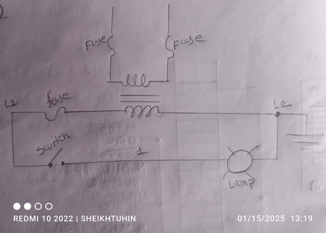
Convert the electrical wiring in the figure below into a ladder diagram.
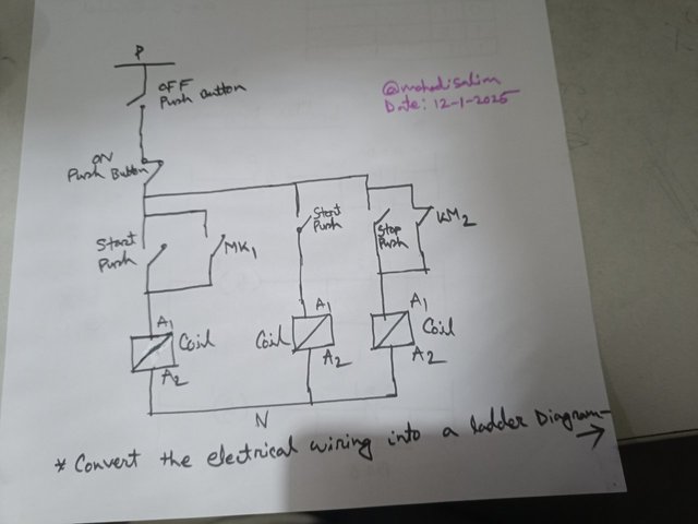
There are several steps to follow to make the ladder diagram in the image above. Step-1A vertical line (power box) should be drawn on the left and a vertical line (neutral box) on the right. Step-2: Add input control button.
Picture of the ladder diagram circuit after conversion.
There are two methods for connecting the batteries.
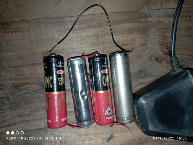
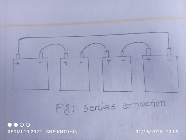
In case of series connection:When batteries are connected in series, the voltage is added but their capacity remains the same. Voltage = 12×4 Capacity = 100 Ah Since the capacitance remains the same in series connection. Connection method:First, you need to put the four batteries together. Connect the positive terminal of the first battery to the negative terminal of the second battery.At the same time, the negative terminal of the third battery must be connected to the positive terminal of the second battery.Connect the positive terminal of the third battery to the negative terminal of the fourth battery.The positive terminal of the fourth battery must be connected to the negative terminal of the first battery.
The picture above shows me making practical connections using a simple pencil battery.At the same time, I will try to show it through the image below.
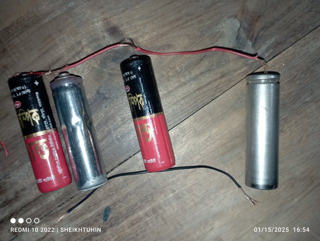
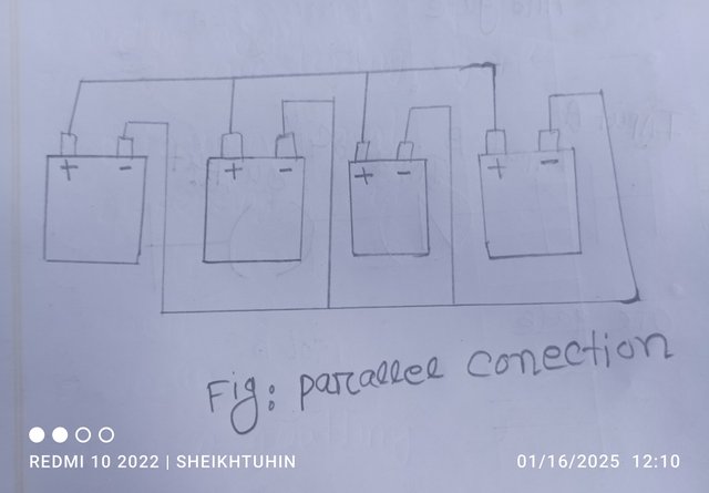
In case of parallel connection:In parallel connection, the voltage remains unchanged but the capacitance changes.The capacity of four batteries is added. Parallel connection method:Voltage= 12 V Capacity = 100×4 Ah Connection method:
The picture above shows a parallel connection method using a common pencil battery.
This image shows how to connect it by drawing a picture. 
|
|---|
X promotion
https://x.com/sheikhtuhin24/status/1879782479592300593?t=KuI5P3P6BUDv8CbEXGmIJA&s=19
The post was amazing, I hope you win. I really want to participate in these competitions, but even if I wanted to, I wouldn't be able to, because I understand very little about these topics.
Thank you very much for your valuable comments.I don't understand much about this subject either, but I understand it fairly well, so I tried to do something from my own knowledge, supporting some chapters of physics, so that's all I know.