SLC22/WK5: Ladder Diagram PLC Programming and Solar Power.
Steemian Friends,
Today, I will write the lesson for week 05 of Steemit Learning Challenge 22. In week 05, I will discuss Ladder Diagram PLC Programming and solar power. We learned about PLC hardware last week. This week, we will learn about programming. Companies that make PLCs use a variety of programs. The most popular is the Ladder diagram. We learned about the basics of solar power in Steemit Learning Challenge 21. This week's solar power update will teach you how to connect multiple solar panels and multiple batteries. So without delay, let's start the lesson.
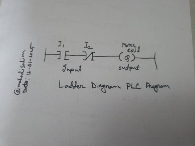
A ladder diagram is a PLC program that converts electrical wiring into machine language wiring. We use symbols to convert electrical wiring through some ladder logic. Ladder diagrams facilitate human use of PLCs by programming electrical signals. For example, we do electrical wiring to turn a switch on or off. Electrical wiring is converted into machine language using ladder diagrams. I have drawn a ladder diagram below.
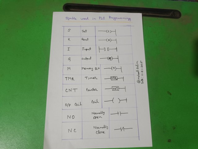
The language in which wiring is used to operate electrical appliances is called a ladder diagram PLC program. I have given below some important symbols and names of the ladder diagram.
The chart has the symbol and name of the ladder diagram. I am writing below the names and functions of some important ladder diagrams. NO and NC are the most commonly used inputs in ladder diagrams. NO is Normally Open. A lamp switch being off is NO. That is, the power supply is off. On the other hand, NC is normally Closed. A light switch is on. If the power is supplied, we will mark the circuit as NC.
Ladder Diagram Output:
A symbol displays the ladder diagram's output. When the input signal is high, the output of the ladder diagram is high, i.e., the motor turns on. The ladder diagram's input and output symbols are very important.
Other ladder symbols include timer (TMR) and counter (CNT). We will learn the ladder symbols given in the chart.
Logic Gate in Ladder Logic Diagram:
We have studied logic gates in electrical and electronic circuits. There are three basic logic gates in electronics.
- AND Gate
- OR Gate
- NOT Gate
Other gates, such as NAND, NOR, X-OR and X-NOR gates.
The ladder diagram also has similar logic gates. We have discussed the AND ladder logic gate below.
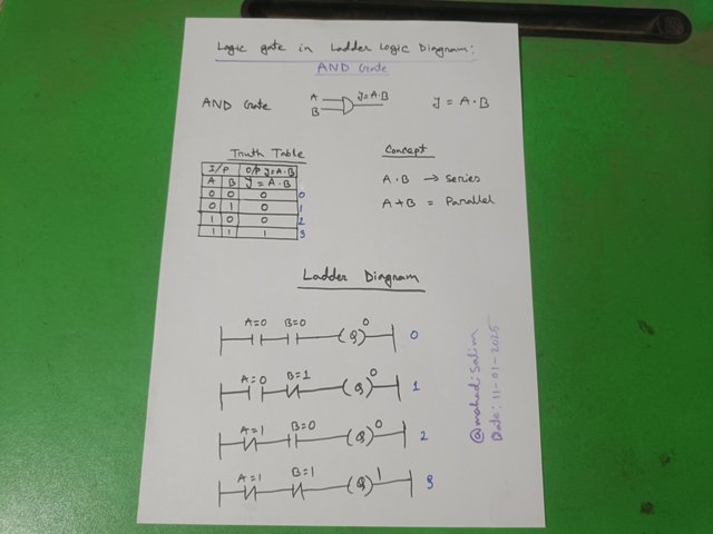
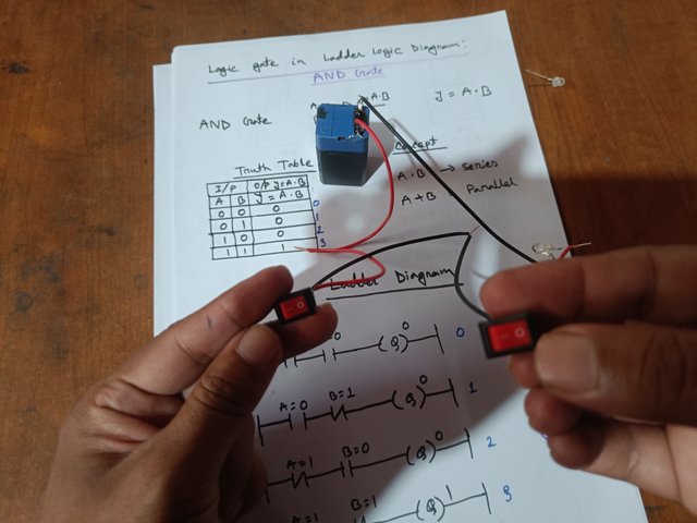
I have drawn the truth table, symbol and ladder diagram of an AND ladder logic gate with two inputs and one output below. The two inputs of the AND gate are denoted as A and B. The output is derived by the formula Y = A.B. A dot (.) in a ladder diagram is the series.
We first get truth tables A=0 and B= 0, and Y = A.B by formula output zero. Here, A=0 means NO (Normally Open), and B=0 means (Normally Open). We know NO means switch off. Since switches A and B are closed, the power supply to the motor's coil at the output is off. The ladder diagram in Figure 0 is constructed using the above process.
| 1 | Switch ON, High, True |
|---|---|
| 0 | Switch OFF, Low, False |
Then, I get zero output by putting the A=0 and B=1 formulas in Y=A.B from the truth table. Here, A=0 means switch off, and B=1 means switch on. However, since the AND gate is a series, the power supply cannot go to the motor when a switch is closed. Hence, zero is found at the output. The ladder is shown in diagram 1 below.
Then input A=1 and B=0 and solve the formula Y=A.B to get output zero. In this case, the first input is switched on, but the second input is zero, meaning the switch is off. So, the output power supply will not be available with a switch closed. As a result, the output motor will not start. Figure 2 shows the ladder diagram drawn.
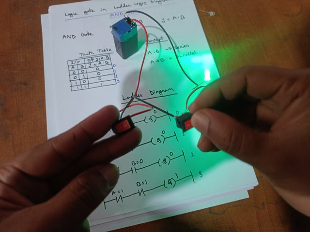
Then, since inputs A=1 and B=1 are high, i.e., two switches are on, the output is shown and on. As the two inputs of the ladder diagram in Fig. are NC, the output motor will turn on. Figure 3 shows the ladder diagram drawn.
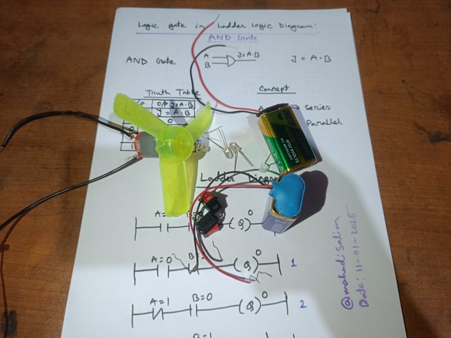
Required Materials:
- Battery (9 Volt) 1 Pcs
- Switch 2 pcs
- LED Light or motor 1 Pcs
Test:
According to the truth table, both switches are off if A= 0, B=0. Both switches are off in the picture, so the LED light is off.
According to the truth table, Switch on when A= 1 and B= 1. The LED lights on the output. In the picture, two switches are on, and the light is on. Thus, we can see the execution of PLC programming with a ladder diagram.
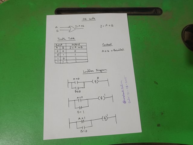
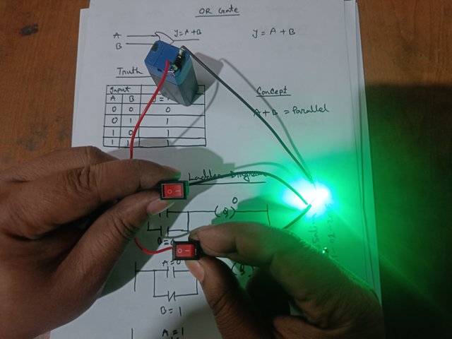
The two inputs' truth table, symbol, and ladder diagram are shown below. The OR gate has two inputs, A and B. Y=A+B denotes the output. The ladder diagram for output Y=A+B (+) shows that Input elements are parallel.
When input A=0 and B=0, the output, Y= A+B, is zero by formula. As we know, A= 0 means switch off, and B=0 means switch off. With both switches closed, the output is zero. The motor will not turn on because there is no power supply at the output.
Then, as input A=0, the switch is off, and as B=1, the switch is on. Since two switches are connected in parallel, when one switch is turned on, the current will flow at the output, and the motor will turn on. The figure shows a ladder diagram.
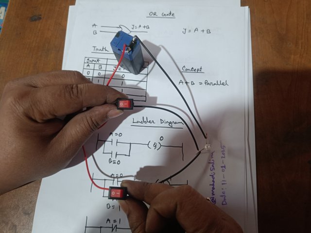
According to the truth table of the OR gate, when A=0 and B=0, both input switches will be OFF. When both switches are closed, the output voltage is not available, so the LED light is off. In the picture, switch two is closed, so the output LED is off.
According to the truth table, if the input is high, the output will be high, that is, the LED light will light up. The LED flashes in the picture after a switch is turned on.
Example:
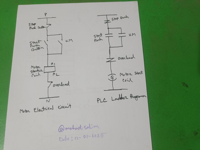
The wiring diagram of an electrical circuit is on the left side of the picture. Electrical symbols of ON push, OFF push, overload, and motor coil are drawn into the circuit. This electrical circuit is converted to PLC with the ladder diagram on the right. NC of the ladder diagram is used to stop pushing. The ladder diagram is drawn with NO symbol for ON PUSH. A motor coil (Q) symbol is drawn as the output of the ladder diagram.
Today, we will discuss three types of solar power. As the use of solar power increases daily, solar power technology is being updated.
- On-Grid Solar Power
- Off Grid Solar Power
- Hybrid Solar Power
On-Grid Solar Electricity:
If the electricity produced from solar panels is directly connected to the grid, it is called on-grid solar electricity. On-grid solar power does not use batteries, so production costs are low. Power is supplied from the grid at night after using solar power during the day. On-grid solar power uses an inverter that converts DC power into AC power.
Advantages:
- As there is no battery, installation cost is low.
- Maintenance cost is low.
- Generated electricity can be earned by sending it to the grid to meet its needs.
Disadvantage:
There is no backup power as there is no battery. At night, electricity is needed from the grid. Projecting such solar power requires a large area of sunlight.
Off-Grid Solar Power:
Off-grid solar power is a method of delivering electricity generated from solar panels directly between batteries and consumers. This method does not require an electricity connection to the grid. Off-grid solar power is most commonly used in homes. It is most effective for areas where there is additional load shedding and no power supply from the grid.
Advantages:
- Backup power is available from the battery when the grid supply is stopped.
- Electricity bill is reduced due to battery backup.
- There is an uninterrupted power supply.
Disadvantages:
Battery consumption increases installation costs. Regular battery maintenance is required. It cannot use more power than the battery capacity. Excess power cannot be sent to the grid. The battery needs to be changed from time to time.
Hybrid Solar Power:
Hybrid solar power has all the advantages of on-grid and off-grid solar power. Money can be earned by collecting the electricity generated by hybrid solar power and sending it to the grid. A battery backup system ensures power supply in case of grid supply failure or even at night.
Advantages:
Uninterrupted power supply through battery backup. Excess electricity generated can be sent to the grid. Battery charge and load supply can be provided simultaneously.
Disadvantages:
Installation cost is high. Battery maintenance costs and periodic battery replacement. It is more complicated than other solar power.
Solar Battery Connection:
Your home has two battery backups for solar power. Now, connect one more battery as your electrical load increases. Then, you have to follow two methods to set up three batteries.
- Battery series connection
- Battery parallel connection
Battery series connection:
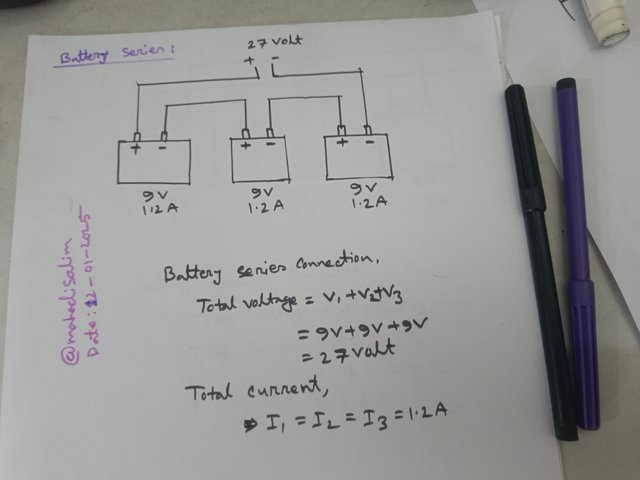
I need to know the voltage and current rating of the battery first. I have shown three 9-volt batteries connected in series below.
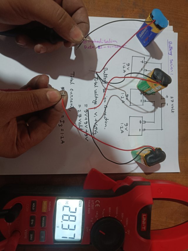
Every battery has two terminals, positive and negative. For a series connection, the positive terminal of the first battery will be connected to the negative terminal of the second battery. In this way, each battery's positive and negative terminals should be connected. I have shown the connection diagram of the three batteries below.
Then, I removed two cables from the positive terminal of the first battery and the negative terminal of the third battery. I measured with a multimeter and found an output voltage of 28 volts.
Formula of Battery Series Circuit: The voltages of each battery will add up.
That is, Total voltage = V1 + V2 + V3 = 9+9+9=27 Volts.
When batteries are connected in series, each battery has the same current.
That is, total current = I1 = I2 = I3 = 1.2 A
Battery Parallel Connection:
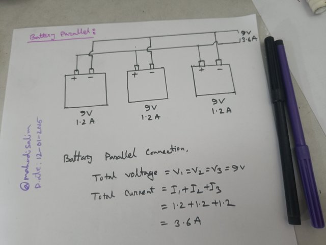
To connect the batteries in parallel, each battery's positive terminals must be connected at one end and the negative terminals at another. I have shown three 9-volt batteries connected in parallel as an example below.
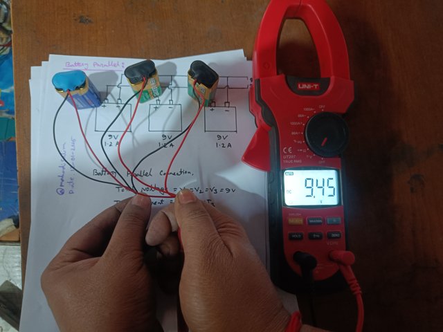
When batteries are connected in parallel, each battery has the same voltage. I've connected three 9-volt batteries below to get a 9-volt output with a multimeter.
The formula for connecting batteries in parallel: If the batteries are connected in parallel, the total voltage is equal to the voltage of each battery.
ie Total voltage = V1 = V2 = V3 = 9 volts.
If the batteries are connected in parallel,
The Total current = I1 + I2 + I3 = 1.2+1.2+1.2 = 3.6 A.
A. What is meant by ladder diagram PLC programming? Draw a ladder diagram and explain.
B. Write the work by drawing the symbols of the input and output elements of the ladder diagram.
C. Draw the ladder diagram with three input ladder logic gates (AND, OR) and explain with practicals.
[With symbols and truth tables]
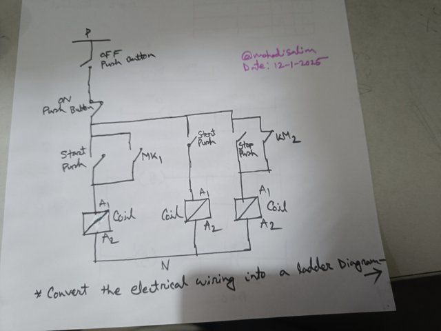
D. Convert the electrical wiring in the figure below into a ladder diagram.
E. Solar power is generated in your home with three 12-volt 100 AH batteries. An additional 12-volt 100 AH battery needs to be connected as your home's electrical load increases. Explain the series and parallel connection of four batteries with diagrams.
[Note: Practical can be done with multiple batteries of any rating.]
Marks Distribution:
| Sl. No | Marks |
|---|---|
| A | 0.5 Mark |
| B | 1 Mark |
| C | 4.5 Marks |
| D | 1.5 Mark |
| E | 2.5 Marks |
- Your title should be " Ladder Diagram PLC Programming and Solar Power."
- The content must be #steemexclusive.
- The article must contain the tag #electricity-s22w5.
- Plagiarism is not allowed.
- The link of your task must be added in the comments of this publication.
- Use the burnsteem25 tag only if you have set the 25% payout to @null.
- You can publish homework in any community and in any language. But don't forget to use the original tag.
- Invite three of your active Steemian friends.
- The participation schedule is between Monday, January 13, 2025, at 00:00 UTC to Sunday, - January 19, 2025, at 23:59 UTC.
SC01/SC02 would check on the entire 15 participating Teaching Teams and Challengers and upvote outstanding content. Upvotes are not guaranteed for all articles.
At the end of the week, we would nominate the top 4 users who had performed well in the contest and would be eligible for votes from SC01/SC02.
Best Regards,
Industrial Electrical Instructor
@mahadisalim



Este es un tema interesante y en el que muchos usuarios tienen interés, las "energías verdes".
En algunas partes no hay servicio eléctrico o el suministro del mismo es limitado, esto es pro diversas causas como falta de inversión, falta de mantenimiento, lejanía de centros poblados o líneas de fluido eléctrico.
Todo esto puede afectar la calidad de vida de unas personas, familias o comunidades enteras.
Por esta razón este tipo de post educativos sirven para que se puedan llevar a cabo tareas de desarrollo de puntos de energía solar.
Le auguro un buen número de participaciones, invito a mis amigos @ubongudofot, @yancar y @lanegra2804 a que participen.
Éxitos en la dinámica.
Saludos
Gracias amigo por la invitación. Bendiciones.
This is my Twitter share link :
https://twitter.com/mahadih83660186/status/1878406615378075948?t=ewxRKEAkzYAVoOGFeHL5cQ&s=19
🤗 encouraging your fantastic post @sheikhtuhin! 🌟
Hey friend! 🎉 Come check out your awesome post on my shiny new front-end! It's still a work in progress but I'd love to hear what you think! View your post here ✨
Here is my link.
https://steemit.com/electricity-s22w5/@asi1993/ladder-diagram-plc-programming-and-solar-power
My entry
https://steemit.com/electricity-s22w5/@sheikhtuhin/ladder-diagram-plc-programming-and-solar-power
My participation link
https://steemit.com/hive-179660/@hamidrizwan/ladder-diagram-plc-programming-and-solar-power
My entry link
https://steemit.com/hive-108451/@moazzamushtaq/slc-s22-w5-or-or-ladder-diagram-plc-programming-and-solar-power
Here is my entry
https://steemit.com/electricity-s22w5/@memamun/slc-s22-w5-or-or-ladder-diagram-plc-programming-and-solar-power
My entry
https://steemit.com/hive-195150/@jozzie90/ladder-diagram-plc-programming-and-solar-power
My entry: https://steemit.com/hive-147599/@toflex/slc22-wk5-ladder-diagram-plc-programming-and-solar-power