This week I am working on enhancing my knowledge of the computer components and
@kouba01's challenges are helping me. I am glad again to join this contest because I am curious to experience more about the field of science to whom I have been linked for the past 11 years. Like the previous one, this contest is a fantasy for me to enjoy as much as possible. A lot of things are waiting to be learned.
Image Edited on Canva
I would use intel Core i3 motherboard to perform upcoming tasks. It is an old but working computer that was installed at my home for public use. So, now move to the topic.
-
Question: Remember your first experience with a motherboard. Did you intend to repair it, or were you just curious to see the inside of a central unit? What was your reaction to this technical complexity? If you have never had this experience, take the time this week to open a central unit and explore its motherboard. Share your observations and impressions, including a photo of your exploration.
This question made me nostalgic and look back to when my father and I went to a computer shop to take our personal computer to diagnose any unknown issue in its hardware components. It is about 5 years ago when I was 14 years in probably in 2019. My first encounter with a motherboard was for both repairing and curious purposes because the mechanic was an old fellow of my father and I helped him to repair the motherboard. Well, that first encounter with the motherboard was certainly unforgettable because when the case was opened, I was surprised to see the buildup of dust on the motherboard components. The after-cleaning scenes also surprised me.
My reaction to Complexity
Arrangement of components
- After cleaning the motherboard through the blower a new and complex appearance of the motherboard for the first time was in my view. It looked complex but everything was well arranged using a strategy. At this time I was unknow of various computer components, especially chips and that day I watched them collectively installed on the same motherboard for the first time.
- Every component was well arranged in its position and the whole motherboard seemed like a drone view of any city shown in Hollywood movies. I viewed the arrangement again and again. It was an organized structure.
Prints & Signs on Board
- Looking at the prints on the motherboard was the same as looking at a map. Footprints of SATA 1, SATA 2, RAM Slot 1, Slot 2, etc resembled directions on a main road in a city. There was no component to whom I could understand.
Ports and Connections
- Many ports, connectors, and small components including capacitors looked like oil or water tanks. In particular, capacitors had a view of heavy oil containers. Smaller components like resisters and thermisters were not easier to understand.
Major Components
- My first exposure to major components like fans, hard drives, power supply units, RAMs, DVD room, and then CPU was strange for me.
- CPU Fan: I put my eye first on the fan on the CPU of that motherboard. The fan was small, and pretty, and as a teenager, I thought of many ideas to use this fan for useful inventions as every teenager tries in life to invent something new like a helicopter or fan for summer use.
- RAMs: After I saw RAMs that resembled the SD card in those days, SD cards were much more common compared to this time. I thought RAMs as big SD chips to store memory. I curiously asked the mechanic; is this a memory storage of this computer? He replied No, it is not. In the answer to the question of what it is, he replied to the word RAM, and adding more he said it is used to process memory stored in Hard Disk Drive, pointing towards HDD.
- Hard Drives: I curiously looked at the HDD. I thought it must store thousands of GBs (no doubt it can) but our HDD had just 80GB of space contained in it. I touched it and it was heavily weighted due to its density; compared to other components.
- Power Supply Unit: Power Supply Unit was commonly used in my city to run various electronic components like fans at that time. Therefore, its exposure was not surprising. I was just a cube-shaped box in which a fan and various components were installed and I raised no question about its presence.
- DVD room: Looking at the DVD was not for the first time. I had watched them from my childhood as they were very common. But, the internal view of the DVD was my first experience.
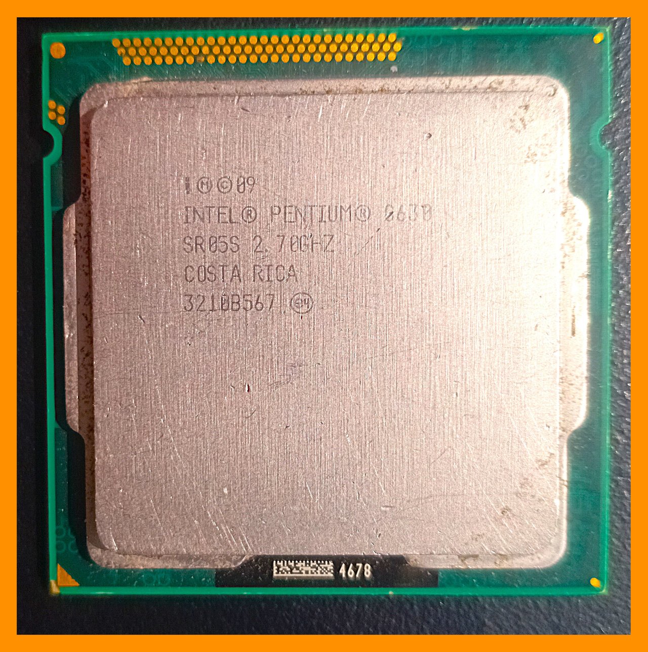
- CPU: It was just a pretty little component. I liked its shape and structure. I still have the same CPU chip.
- PCIe Slots: PCIe slots are used to install GPU commonly. But, they resemble the RAM slots. When I saw PCIe slots for the first time, I considered them extra positions for more RAM chip installation after knowing the RAMs.
- CMOS Battery: It is used to give enough power to the BIOS. Looking for the first time, I thought it was only used to keep the Time and Date up to date. I was unaware of the importance of providing power to the BIOS setup when the computer is turned off.
- Southern Bridge: It looked like a CPU due to its tiny pretty looks. There was a thin layer of dust on it and I have clearly remembered that I cleaned that with my ring finder and then I saw the layer of dust on that finger. After the dust had cleared, a glassy face of chip appeared and I tried to watch my eyes and face in that. However, I considered it a sub-CPU at that time.
To avoid length burden, pictures in one frame.

-
Question: Take a photo of a motherboard, either your PC's or another PC's. Identify and name its main components, specifying their role. Describe the processor socket, RAM slots, chipset, PCIe ports, SATA and M.2 connectors, power connectors, CMOS battery, and any other visible elements. Also indicate the model of the motherboard studied.
| Model of my Motherboard: DELL Optiplex 3020 Motherboard with 040DDP baseboard product and A01 version |
|---|
| 1. PCIe x16 & PCIe x1 Slots |
|---|
- It is a PCIe (Peripheral Component Interconnect Express) type slot. It is used to install GPU and expansion cards. It is the largest component on the motherboard by its lanes. It has x4 wired lanes allowing multiple gigabytes to process through it in one second; therefore, it is a component of higher importance. It has several types and generations. The PCIe installed in my motherboard has a Bandwidth of 4GB/s along with x4 lanes activation.
- It can provide the power of 75 Watts to the GPU or expansion installed in it. As discussed in the previous contest, the GPU cards requiring more power need extra power cables. Anyways, its compatibility, power, generation, and model are completely suitable for various modern GPUs. It is a mid-performance reliable version because it is still in industrial standard, presenting that the manufacturing industries prefer to use it for modern GPUs and expansion cards.
- PCIe x1 is another slot installed on motherboard. It is slower than PCIe x16. It has only one lane which means it transfers data slower than x16 and is used for limited purposes. It can transfer up to 500MB/s.
- Though its limitations allows some specific functions to perform. Lower WIFI or Internet LAN cards, Sound Cards and USB cards can be installed in it. It consumes low watts of power ranging from 2-8 Watts depending on the specificity of the card installed in this slot.
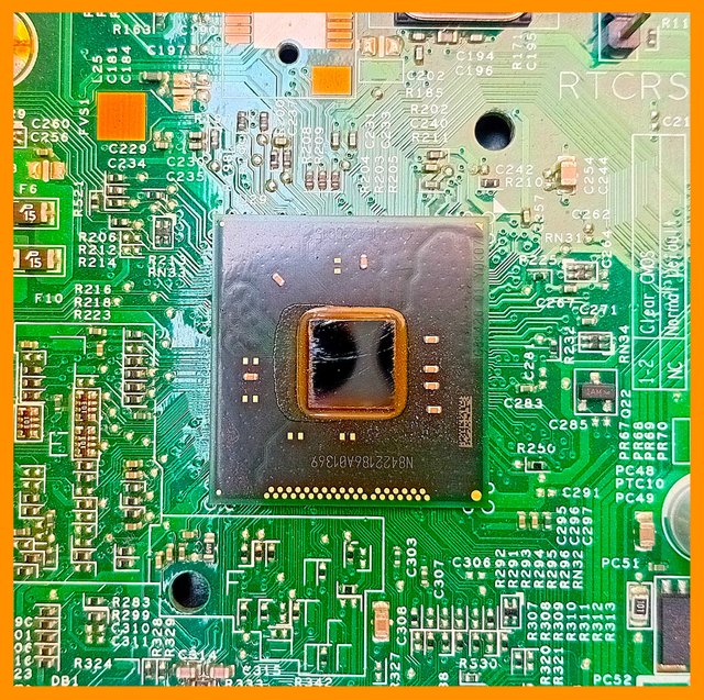
| Chipset (Southern & Northen Bridge) |
|---|
History and Revolution
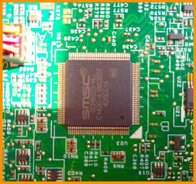
- There was a time when a lot of smaller chips were present on the older motherboards. As time passed, the technology revolutionized and a large number of clips were replaced by only two chips known as South Bridge and North Bridge, and they are collectively called chipsets.
Northern Brigdge (On Left)
- The picture on the left side shows a North Bridge installed on my motherboard. The northbridge is located in the upper or northern part of the motherboard, provided you're looking at the motherboard in the upright position. It's located near the CPU and is directly connected to the CPU. It's also directly connected to the memory (RAMs) PCIe slots. Now it has a direct connection with CPU RAMs and PCIe slots. So for the CPU to communicate with the memory and the AGP or PCI-Express bus, it has to go through the Northbridge first. So the northbridge acts like a communication middleman between the CPU, PCIe, and memory (RAMs).
Southern Brigdge (On Right)
- The other chip is called the south bridge and the southbridge is located at the bottom or southern portion of the
motherboard, near the PCI bus slots The southbridge connects to the PCI bus slots, SATA, and IDE connectors, and USB ports. So the southbridge is responsible for the lower portion of the motherboard. While the northbridge is responsible for the upper portion. There is no direct connection between the CPU and the lower portion of the motherboard. So if the PCIe, USB, or SATA ports are needed to communicate with the CPU, the information has to go through the south bridge and then up through the northbridge and then to the CPU.
|
|
|
|---|
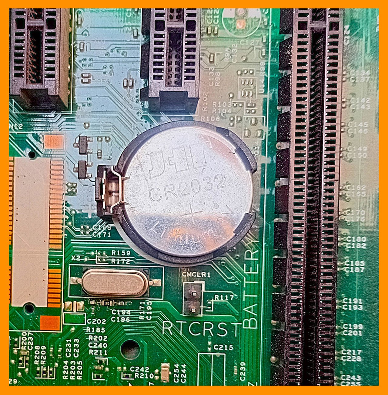
- There is a CMOS chip present in a large integrated circuit of the motherboard of the South Bridge. CMOS chips are used to store the current date and time, boot sequence, hardware configuration details, and other BIOS settings. This information must be sequenced according to the default settings even when the system is turned off. To keep these settings default battery or coin cell is used to provide voltages to the CMOS chipset to keep the settings default. This is known as a CMOS battery.
- CMOS Battery also known as BIOS battery or Lithium coin cell is used to power the CMOS chip even when the motherboard is turned off. It remains always active. My motherboard has a 3V and 220mAh CMOS battery.
- Failure of this battery results in the loss of BIOS settings like time and date. Moreover, the motherboard can cause complications like not recognizing the devices properly and many software including the internet browsers do not work properly.
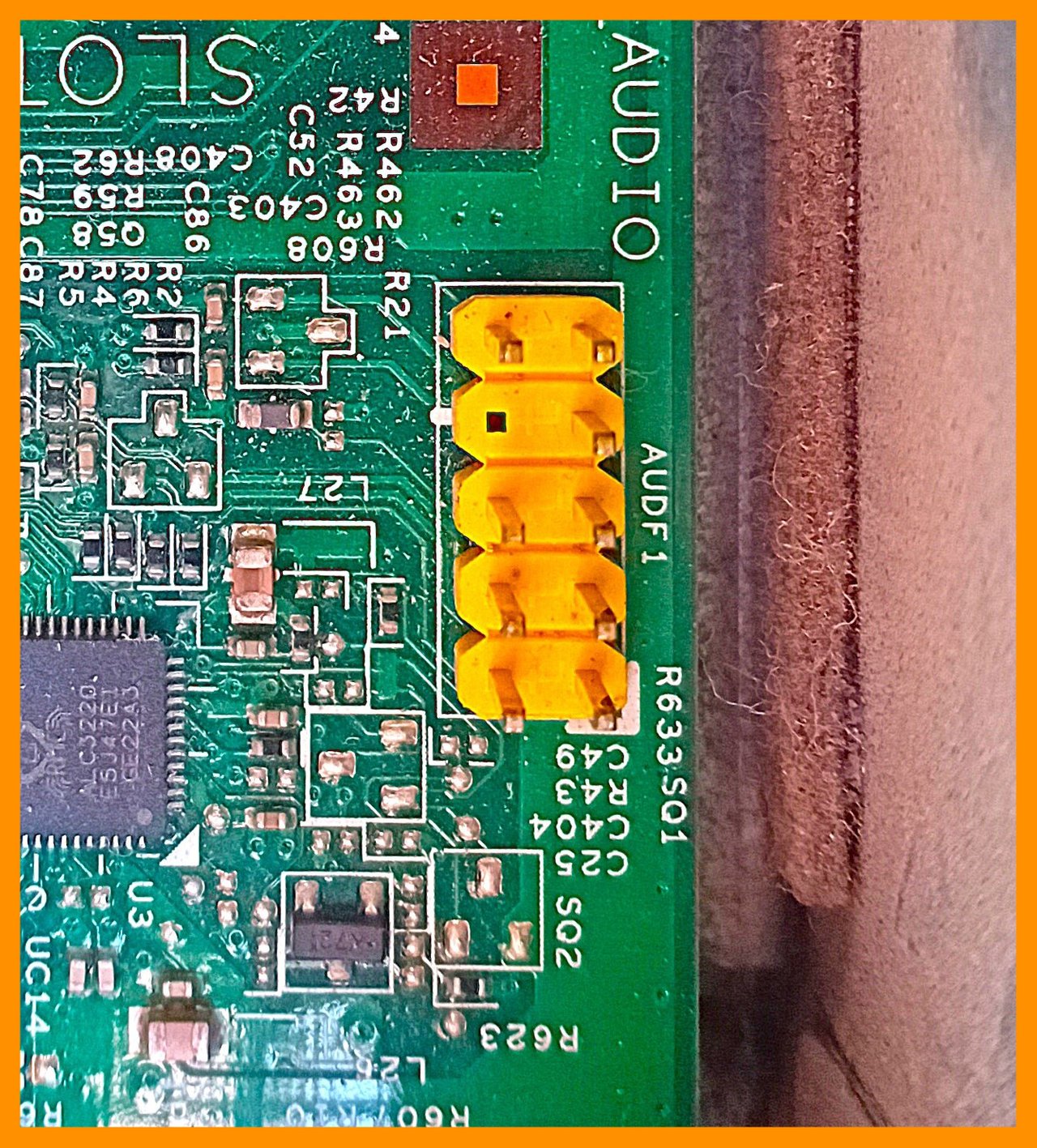
- This connection is used to give inputs to the front audio slots like microphone and headset devices. It is a component of importance giving power and data to the external devices and receiving signals from them.
- Function, voltages, color, and serials are given in the below table.
| Number | Color | Thickness | Function |
|---|
| 1 | ⚫ Black | Thick | Ground (GND) |
| 2 | ⚫ Black | Thick | Ground (GND) |
| 3 | ⚫ Black | Thick | Ground (GND) |
| 4 | Brown | Thin | Mic Bias (Power for Mic) |
| 5 | Red | Thin | VCC (+5V Power) |
| 6 | Orange | Thin | Mic Left Channel Input |
| 7 | Blue | Thin | Mic Right Channel Input |
| 8 | Yellow | Thin | Front Right Audio Output |
| 9 | ⚫ Black | Thin | Front Left Audio Output |
| 10 | ❌ Empty Space | - | No Connection (NC) |
- Following are the USB front penal pictures. This section is the main to receive data and gives power to the front USB. Without its plugins, the front USB ports do not work. Therefore, it deals with the higher important data transfer system.
- Each colored wires carries a distinct important feature. This port also plays an important function in accelerating the microphone. Following is the table of functions.
| Number | Color | Thickness | Function |
|---|
| 1 | ⚫ Black | Thick | Ground (GND) |
| 2 | ⚫ Black | Thick | Ground (GND) |
| 3 | ⚫ Black | Thick | Ground (GND) |
| 4 | Brown | Thin | Mic Bias (Power for Mic) |
| 5 | Red | Thin | VCC (+5V Power) |
| 6 | Orange | Thin | Mic Left Channel Input |
| 7 | Blue | Thin | Mic Right Channel Input |
| 8 | Purple | Thin | Front Right Audio Output |
| 9 | ⚪ White | Thin | Front Left Audio Output |
| 10 | ❌ Empty | - | No Connection (NC) |
- SATA data slots play an important function in reading data present in HDD_ODD (DVD/CD). These devices require a large amount of power and voltages. A data cable must be able to fulfill the requirements of the installed devices.
- There are four slots on this motherboard starting from zero to 3 numerals. However, the plastic slot has not been installed on the 3rd number circuit because it is not needed.
- The data cable on the right side is the cable installed in my motherboard to carry data from HDD_ODD. It is a secure cable in its looks and can transfer data up to 6 GB/s. These wires have no logic and circuitry inside them. They are just cables. There is no impact of different colors of cables. These colors are just used to make the machine aesthetically pleasing.
- These cables installed in the slots have 26 AWG (American Wire Guage) thickness. It can bear temperature upto 80oC and can carry up to 30V potential.
| Properties | Specifications |
|---|
| Model | E209329 |
| Max. Temp. | 80oC |
| Voltage | 30V |
| Thickness | 26 AWG |
| Rate | 6 GB/s |
- In this slot, a female port is connected with two wires moving to the front LED element.
- It also confirms the system responsiveness and if it keeps on continuing blinking, then it might indicate any background progress on the driver such as scanning and updating.
| Number | Color | Function |
|---|
| 1 | Red | Power |
| 2 | ⚫ Black | Ground (GND) |
| 3 | ⚫ Black(3+6) | Ground (GND) |
| 4 | ❌ Empty | No Connection |
| 5 | ⚫ Black (5+7) | Connected to Same Slot |
| 6 | ⚫ Black (Loop 2) | Connected to Same Slot |
| 7 | ⚫ Black (Loop 2) | Connected to Same Slot |
| 8 | ❌ Empty | No Connection |
| 9 | ❌ Empty | No Connection |
| 10 | ❌ Empty | No Connection |
| 11 | ❌ Empty | No Connection |
| 12 | ❌ Empty | No Connection |
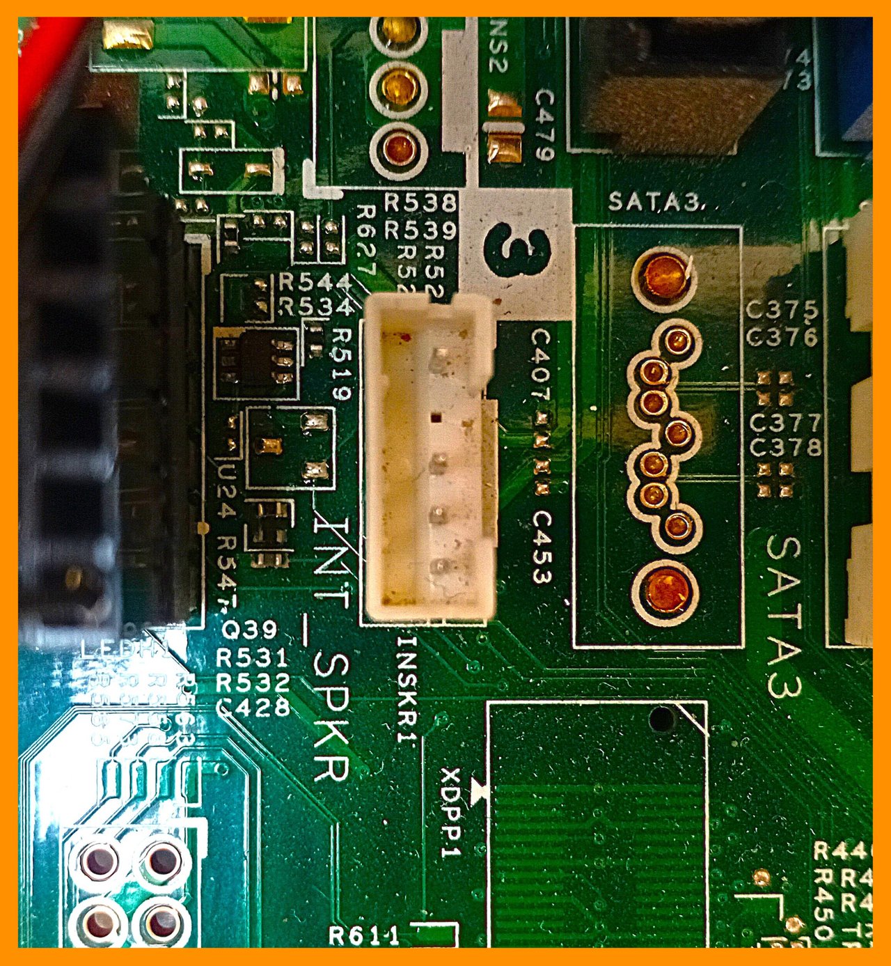
- Intel motherboards have a preinstalled mini speaker which is used to give beep sounds as well as small-volume audio. It has a total of four wires or connections shown in the picture on the right. Two wires leaving or entering the circuit work as power wires. One is red at +5V and the other is black; ground wire. There is a loop forming U shape is forms a jumping connection which is used for signal continuity. One space in the pins presents that only two pins are under use while the empty one is useless and plays no role.
- This speaker has been installed to mainly perform the functions of beep sounds. Beep sounds play important functions listed below.
| Number | Beep Code | Function |
|---|
| 1 | 1 Short Beep | System Boot Successful |
| 2 | 2 Short Beeps | CMOS Setting Issue |
| 3 | Constant Beep | RAM or Power Failure |
| 4 | 3 Long Beeps | GPU Not Detected |
| 5 | 5 Short Beeps | Processor Failure |
| 6 | No Beep | Power Supply or Motherboard Failure |
| Hard Disc Drive Power or Optical Disc Drive Power |
|---|
- This component provides power to the Hard Disk Drive and Optical Disc Drive (ODD). One lane of this slot makes a connection with the Hard Dic Drive while the other lane makes a connection with the Optical Disc Drive in the Optiplex 3020 motherboard. Each color carries its importance and the following is given a table of all colors, functions, and pins. Therefore, it carries
- The separate images of plugged and unplugged slots could not be available as it remained difficult for me to unplug this connection. To prevent any mechanical loos, I kept it plugged in as there is no backup of this connection.
| Pin No. # | Color | Function |
|---|
| 1 | ⚫ 2 Black (Same) | Ground (GND) |
| 2 | Orange | +3.3V Power |
| 3 | Red | +5V Power |
| 4 | Yellow | +12V Power |
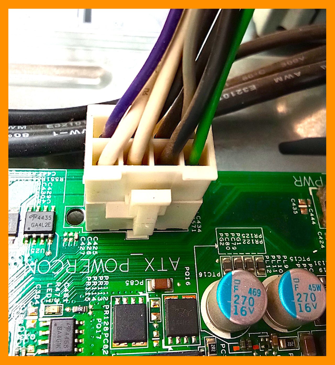
- It is the main power link that gives power to all components on the motherboard. It is also known as the motherboard's main power connection. Eight wires are coming into the socket. Each wire has a distinct color. Nonetheless, this is one of the most important connections given to the CPU and is especially important to power up all the components. Failure of this connection results in the shutting down of all the CPU functions. Below is a table to explain each wire briefly.
- A strange thing is the +12V for white while it belongs to yellow color. Actually, in Dell Optiplex 3020, Dell uses white color instead of yellow for +12V for main motherboard power. Unlike normal ATX, Dell uses white color to customize and that is why the color scheme or codes are a little bit different in Optiplexes.
| Number | Color | Voltage | Function |
|---|
| 1 | ⚪ White | +12V | Processor Power (+12V) |
| 2 | ⚪ White | +12V | Processor Power (+12V) |
| 3 | ⚫ Black | 0V | Ground (GND) |
| 4 | ⚫ Black | 0V | Ground (GND) |
| 5 | ⚫ Black | 0V | Ground (GND) |
| 6 | Purple | 5VSB | Standby Power (+5V) |
| 7 | Gray | PWR_OK | Power Good Signal |
| 8 | Green | 0V | Power On (PSU Control) |
| Random Access Memory (RAM) |
|---|
- RAM slot is a space or place where RAM (Random Access Memory) is installed. My motherboard has DDR3-type RAM slots and only DDR3-type RAMs can be installed in it. Each of the slots gives 1.5 voltages.
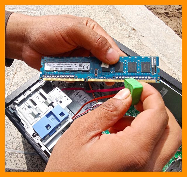
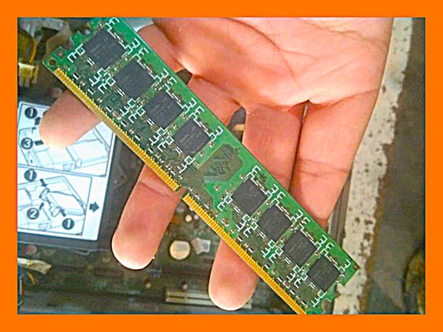
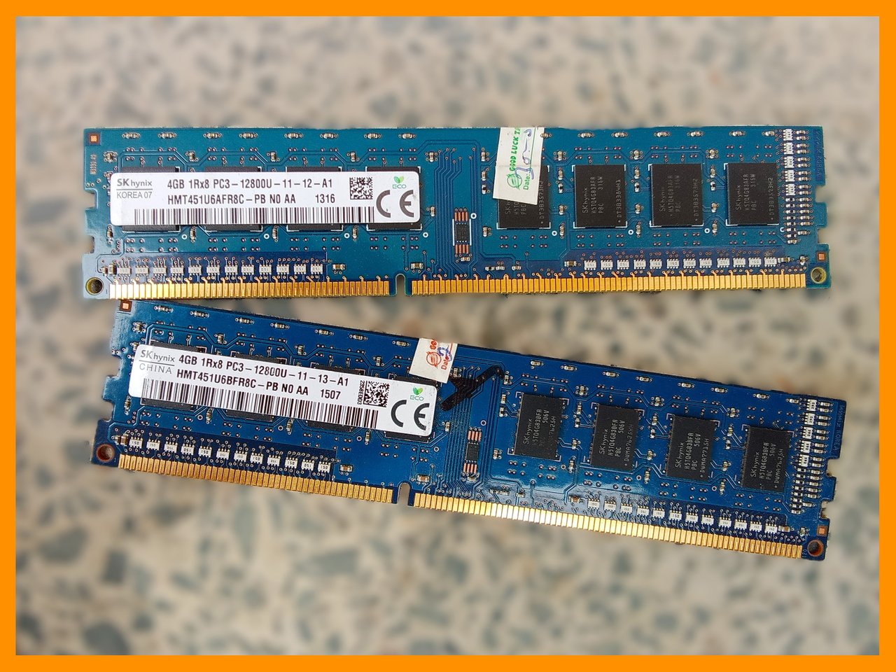
- The picture on the right presents the plugged image of RAMs. These RAMs are DDR3 type and are UDIMM (unbuffered dual in-line memory module) shape RAMs. UDIMM is designed only for desktop computers, not for laptops. They are designed for the performance of higher tasks and are commonly used in workstations. They have performed more than normal DIMM. Here is a small table to present the details about the RAMs installed on the motherboard.
| Slot #1 | Specifications | Slot #2 | Specifications |
|---|
| Max. Bandwidth | PC3-12800 (800 MHz) | Max. Bandwidth | PC3-12800 (800 MHz) |
| Module Mfg. | SK Hynix | Module Mfg. | SK Hynix |
| DRAM Mfg. | SK Hynix | DRAM Mfg. | SK Hynix |
| Part Num. | HMT451U6AFR8C-PB | Part Num. | HMT451U6AFR8C-PB |
| Serial Num. | 2D4229F1 | Serial Num. | 024C8EC9 |
| Size | 4 GBytes | Size | 4 GBytes |
| Central Processing Unit Power Connection |
|---|
- CPU power connection is a slot or point where the power to the CPU is given through a physical wire. ATX2 written on the right side of the connection shows the ATX connection with the CPU.
- CPU works like a brain in the human body. It carries less than 1% of the total body's weight but requires a lot of power and energy to work. Similarly, the CPU functions in this model as a brain works in our body. It requires a lot of power.
- Each yellow wire presents +12V DC whereas each black wire is for ground. It can deliver 192W power from it. It is only designed for the CPU.
| Wire Color | Function |
|---|
| Yellow | +12V |
| Yellow | +12V |
| ⚫ Black | Ground |
| ⚫ Black | Ground |
| Central Processing Unit Fan |
|---|
- CPU fan is used to exhaust the heat from the CPU produced during the processing. It is a fundamental component of all motherboards.
| Pin Number | Color | Function | Voltage |
|---|
| 1 | Blue | Speed Control (PWM) | Variable |
| 2 | ⚫ Black | Ground (GND) | 0V |
| 3 | Red | +12V Power Supply | +12V |
| 4 | Yellow | Tachometer (RPM signal) | Variable |

- Question: Take pictures of the back of the PC to capture the external ports. Identify the different ports and explain their functions. Compare USB, HDMI, DisplayPort, VGA, Ethernet, audio jack, PS/2, and any other available ports. Detail their uses and differences.
| Description | Image |
|---|
| VGA stands for Video Graphic Array. It is commonly used in Dell motherboards. It is also a part of my motherboard and provides videos up to 1920x1080 resolution. It transports analog signals from the motherboard to the main screen supporting RGB colors, it has vast diversity in graphics. It is a 15-pin D-shaped input slot. It does not support audio when plugged in. It has a vast diversity of uses but I use a high-resolution Display Port rather than a 15-pin VGA. | 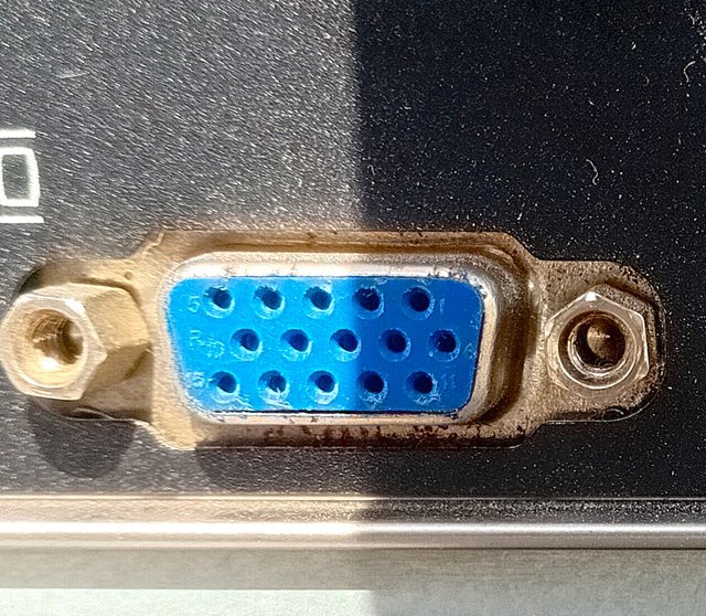 |
| Pin # | Functions |
|---|
| 1 | It is responsible for Red color videos |
| 2 | It is responsible for Green color videos |
| 3 | It is responsible for Blue color videos |
| 4 | Ground |
| 5 | Ground |
| 6 | Red Ground |
| 7 | Green Ground |
| 8 | Blue Ground |
| 9 | It provides +5V potential in some cases. |
| 10 | RND (Reserved, Not Defined). |
| 11 | Reserved or Empty (with a male pin). |
| 12 | It is used to monitor communication. |
| 13 | Controls Horizontal Sync (H-Sync), which means that the new line of pixels is drawn before moving to the next row. |
| 14 | Performs similar to pin-13 but in the vertical position (from top to bottom). |
| 15 | I just know that it provides the clock signal, which enables the monitor to communicate. |
| Description | Image |
|---|
| This is a DP (Display Port) cable slot with version 1.2 with 4K @ 60Hz (3840×2160) maximum resolution. It is a HDMI compatible slot and is even used in the most recent workstations and gaming computers. I use it for my display screen while it gives High Definition display. It consumes about 1.6 watts of power. An interesting fact about this slot is the back compatibility. It can be replaced by VGA and HDMI. | 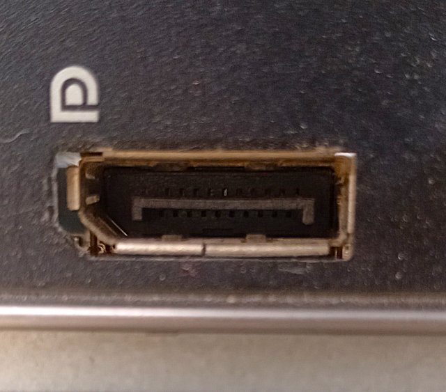 |
| Description | Image |
|---|
| The green port is lane-out or speaker-out. It is a port or slot in which the speaker wire is plugged in and the volume output is obtained. It is also used for plugging in headphones. But it is only used to obtain output results not to give input commands. The other port is lane-in which is used to plug in a microphone or any other input device. It is used for an external microphone. It is common in all system motherboards and is used extensively. | 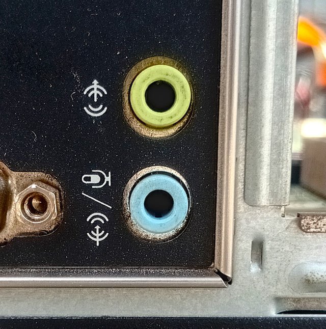 |
| Description | Image |
|---|
| This is a well-known USB port with version 3.0 USB files. This SS sign on the left side stands for Super Speed. It can give current up to 900mA and 5Gb/s. It has some features like faster, powerful, compatible, and gives a high and better performance. Even if someone wants to connect an external SSB, this port is most compatible and better for such more power-requiring devices. | 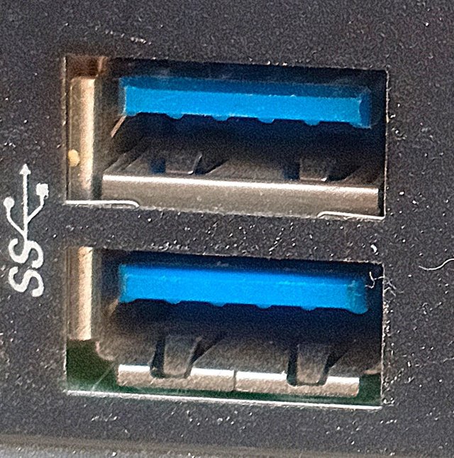 |
| Description | Image |
|---|
| This is an Ethernet port that is found in almost all modern computers. It is used to receive internet LAN cable and is highly stable. It has different colored LEDs and each color indicates a particular process for internet progress. It is a multi-use device. It is used for internet LAN wires, for connecting routers, and for high-speed data transfer to wifi. | 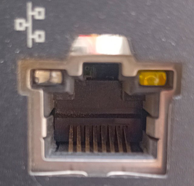_20250224_120202.jpg) |
| Description | Image |
|---|
| This is a picture of USB 2.0 with a + sign which suggests that it is compatible with charging devices and is more effective than the morally used 2.0 USB slots. It can also be used for faster data transmission with a speed of 480 Mb/s while it consumes a current of 500 mA. | 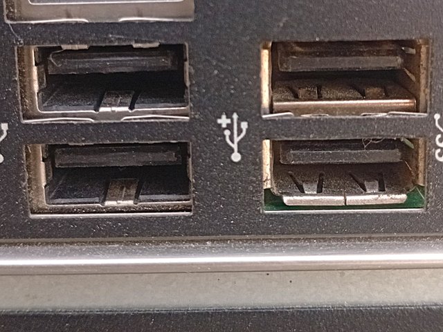 |

- Question: Have you ever encountered a failure affecting your PC’s motherboard? If yes, explain the failure and how you fixed it. If not, mention some common failures such as power supply problems, BIOS problems, overheating components, swollen capacitors, or faulty RAM. Describe possible solutions for each problem.
| Power Supply Unit Failure |
|---|
- There could be many reasons behind the failure of the PSU like compatibility issues, power surges, sudden power shock, and overheating of internal components but all these problems lead to the shutting down of PSU.
Diagnosis
- Power supply failure may be diagnosed by overheating, shutting down, or not starting the power supply, restarting the system while normally functioning without command, burning smell, a noise like a buzzer and clicking failure, and the breakage of the local circuit breaker if it is installed. Each sign reflects the severity of different levels.
Solutions
- Several steps should be taken after the diagnosis of PSU failure. Some of them are mentioned like checking the power connections which is the most basic and very fast to take.
- If a power supply faces any loose connection then after making a strong power bond can run the PSU to work.
- Another step to take in this respect is to check the power outlet of the surge protector and especially the power slots of the outlet. This is the basic most but an important step to test by self through sense. If the power outlet slots have any technical issues then there is no need to diagnose the PSU. This can be done by plugging other devices into the same outlet to check functioning.
- Using paperclip technique can verify the PSU life. This is done by connecting black and green wires using paperclip.
- Now, the fan is not spinning, then using a multimeter test and further confirm the death of the PSU and can indicate the replacement of the PSU. This method includes the measurement of voltages through different rails. For as they meet the standardized values of voltages like +3.3V, +5V, and +12V when the PSU is normal and can perform functions but if the voltage values are beyond the normal range, then the PSU is faulty.
- The last solution includes the replacement of the PSU when it is completely dead and cannot be repaired anymore. This is an easy step for many users.
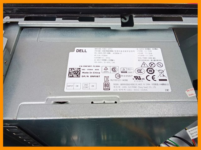
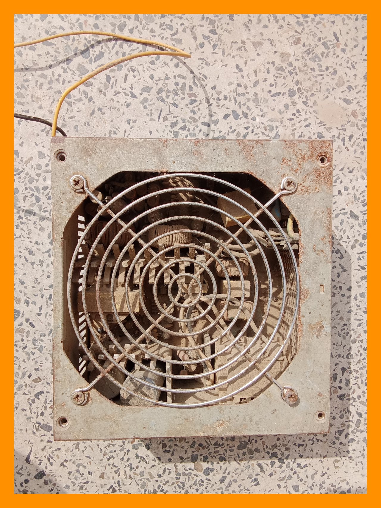
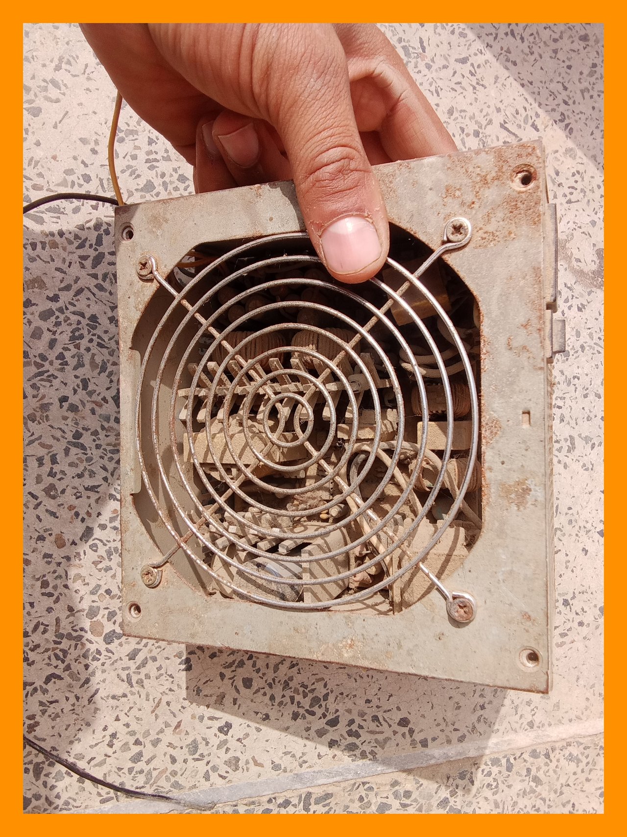
PSU shown in the above pictures presents the cutting of wires and dust around the component. There is no physical damage like burn except the cutting of wires. The first step is to join the proper wires with it and then using the paper clipboard technique, it should be tested. But, there is just cutting of wire issue present in this PSU.
- BIOS may fail as the result of any failed update if someone updates his computer BIOS and the update is not complete then the whole BIOS fails and the motherboard becomes unbootable. But one of the most common issues that cause BIOS failure is the failure of the CMOS battery which gives power to the BIOS when this battery fails the BIOS becomes powerless when the PC is turned off and the BIOS may reset or it can behave as a failed operation. Malware infection and sometimes hardware compatibility may also become a reason for the failure of BIOS.
- Some steps should be taken when BIOS fails on any computer. The first step includes resetting the BIOS. In this process the CMOS battery is removed and then plugged again into the motherboard and the BIOS setting resets leading to the total reset of BIOS this removes any faulty command from BIOS.
- If the previous step fails, then BIOS should be updated manually using a flash drive which is an effective step to restore the functionality of BIOS settings.
- Many motherboards have already been installed in recovery mode which recovers BIOS failure such motherboards have BIObackupsup which restores the restore files automatically the BIOS failure is due to CMOS battery failure then it can be put back by changing the battery the way the above-mentioned steps are useful and almost these are the only steps to recover the BIOS.
The power supply unit shown in the above picture is an old out power supply which has several problems like as capacitors diodes Transformers and resistor moreover it has no output cables along with its several components are removed but there is no component in this power supply to work properly and hence it requires total replacement.
| Overheating ️ & Solutions |
|---|
In a computer system, each component has a certain temperature value to perform the best of its functions and a maximum temperature that a component can bear, and beyond the boundaries of that temperature, any component shows a decline in performance. This is known as overheating.
Diagnosis
Overheating can be diagnosed by using particular software like Core Temp or HWMonitor.
Solutions
- One of the most common issues causing overheating of components is the buildup of dust on the terminal motherboard components or the power supply unit. When a large amount of dust accumulates, it can cause overheating. The simple chemistry behind this is that dust may contain chemicals or compounds that capture and trap heat.
- Another reason for overheating due to dust is that it covers heat-sensitive parts like fans and heat sinks. This layer of dust blocks these components to exhaust heat properly. While this discussion is not directly related to the title, it is important to understand the role of dust in raising temperatures. Therefore, cleaning the components is a crucial first step to avoid overheating. There are several devices available for dust removal, which are discussed in a later section.
- Usually, the thermal paste remains effective for 1-3 years, after which its replacement becomes essential. If not replaced, the CPU may start to overheat. Reapplying thermal paste is another solution to reduce component overheating.
- Providing a proper ventilating environment for a computer system is a small but important step that many users overlook. Ignoring this step can lead to complications and reduce the lifespan of components. Ensuring proper airflow through the system not only increases component longevity but also enhances productivity by maintaining speed and reducing overheating. This step should be considered an essential solution to overheating issues.
- Replacing the normal cooling system with a liquid cooking system is an advanced method to avoid heating.
| Swallon or Leaked Capacitors & Solutions |
|---|
Capacitors play an important role in stabilizing the flow of current inside the motherboard and are crucial for the proper functioning of each component. Their swallowing or leakage affects the functions of the whole system directly and indirectly therefore, they must be kept an eye on them.
Diagnosis
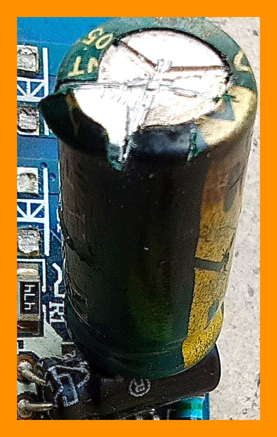
Swallowed or leakage of capacitors can be identified by their physical shape and structure. Usually leaked capacitor is ruptured from one of its positions on the body while a swallowed capacitor increases its volume and looks different from other capacitors.
Solutions
- The 1st and most crucial step that we can take against capacitors is to replace them immediately but this requires high professional skill because there may be many small integrated circuits around that particular capacitor and any mistake can lead to further complexities. This step to repair or replace the swelling capacitor by itself should be only done when one is professional in holding a solder.
- The above-mentioned advice is more than a solution. The steps against swelling or leaked capacitors is to take preventive measures to avoid this hazard. Overall, there are two causes behind the capacitor issues. One is the aging of capacitors and the second is the direct or indirect effect of other components on capacitors. We can have nothing to do with the aging of capacitors because it is an irreversible process and after a certain age, they must be changed. But what we can do is take preventive measures to avoid swelling or leakage of capacitors.
- The first step we can take is to use a high-quality power supply unit with at least 80 PLUS bronze certificates. This step is used to take against capacitor production because a low-quality power supply unit can provide unstable voltage leading to power spikes and power issues leading the capacitors to shorten their life span. Moreover, low-quality power supply units can cause both swelling and leakage of capacitors.
- Above are not only the preventive steps but also the solution to the problem because, in my point of view, a swollen or leaked capacitor must be replaced. However, the above steps can minimize destructive hazards.
There are two capacitors shown in the above picture one of them is a leaked capacitor on the left and the other one is a burnt or swollen capacitor on the right side both of these capacitors also need to be replaced as immediately as possible and this is a picture of computer component an external computer component.
- RAM stands for random access memory which is a crucial component to store data in computers temporarily and for quick access. If RAM faces any problem then the whole system has its impact and in many cases, the system does not show Windows desktop either.
Reasons
- There can be many reasons behind the failure of RAM like manufacturing, improper installation, overheating, software issues, power surges, and other electrical issues RAM can be diagnosed by random crashes of windows without warning BSOD, on-screen failure to boot, or unusual beeping sounds along with performance issues.
- Test the RAM in different slots because there may be a technical issue with that particular slot in which RAM is installed therefore by changing the RAM slot this issue can be go through.
- Checking the overheating is the second step to the solution of RAM because overheating can cause performance issues in RAM, and if the RAM is heated then heatsink cases should be used on the RAM to avoid overheating. Moreover updating RAM to a good manufacturing can also lead to enhancing lifespan and solving RAM issues.
- Sometimes an older RAM may collect carbon on its golden chip print causing hurdles in the transformation of data and leading to low performance of RAM. This carbon can be cleaned by using a school geometry eraser.
- If RAM fails after applying the above-mentioned steps the one step that remains is to replace the RAM using a compatible and more qualified RAM to the motherboard
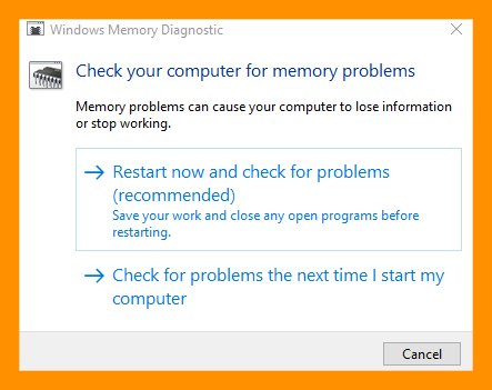
- Sometimes memory diagnose test proves helpful in diagnosing and soRAM the RAM problem for this purpose use
Win + R to open RunWindows windows and then put mdsched.exe, hit enter then click the option restart now and check for the problem This will automatically detect the error and can repair minor software errors.
| Using Eraser | Diagnose & Solution test | Dead RAM |
|---|
 |  |  |
The above picture (on the rightmost) of random access memory presents the spark of integrated circuits on RAM and this is useless RAM. Replacement is the only option to solve this problem of RAM.

- Question: How can you prevent dust accumulation, overheating, and power surges? Why is it important to check component compatibility and connections? What are the risks associated with BIOS updates and humidity?
| Prevention for Dust Accumulation |
|---|
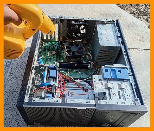
- There is only one way to prevent the motherboard from dust accumulation that is to clean it regularly. It may be daily cleaning, after a week or a month. But, it should not be delayed to the interval of a year. At least, a motherboard must be cleaned after each month to prevent the accumulation of dust from it. Following are some ways to keep the motherboard clean. Like using an electrical blower shown in the below picture. I have that in my home to clean my computer and I have set the cleaning on a weekly frequency.
- Cleaning with a blower can be damaged sometimes because a blower throws air at a high rate and it can damage sensitive transistors especially capacitors installed on the motherboard. Therefore, using an intake vacuum pump is is more safe to use.
- Moreover, using a soft brush to perform this task may help in that case when machines are not available. But, keeping in mind that the computer motherboard has sensitive chips, the hardness of the brush should be minimal.
| Blower | Brushing |
|---|
 |  |
| Prevention against Overheating |
|---|
- The first step to prevent overheating is to place the computer in an airy and fresh environment with proper ventilation of air. The environment should not be humid due to the corrosion of the components. Like keeping the computer near a window or any other opening.
- The next step is to use the high-quality thermal paste to exhaust the heat properly from components, especially from the CPU.
- Here, the previous steps came again, cleanings. It is an important step to keep the motherboard clean from dust to only to prevent the buildup of dust but also to prevent overheating because dust may cause friction, absorption of heat, or malfunctioning of components. Cleaning is an important step.
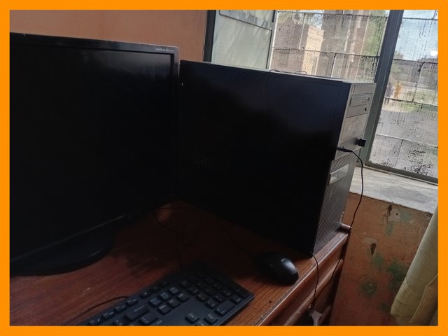
Ventilation of my Personal Computer to avoid overheating
| Power Surge and Solutions |
|---|
- A power Surge is a sudden spike in the electrical voltages that can cause damage to the electrical components. To avoid this, a high-performance power supply should be in computers. A power supply with an 80-plus performance certificate is a high-performance power supply unit. At least this type of PSU should be used to prevent power surge.
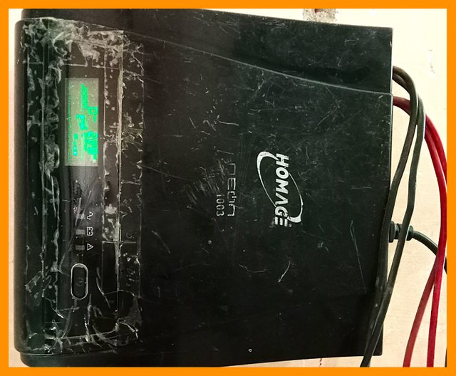
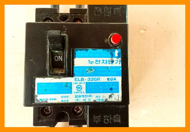
- Many UPS, stabilizers, or external power supplies can control the voltages under a specific range. This is a useful but expensive way to prevent the power surge but, it is more safe to damage components. Moreover, using a circuit breaker can help to avoid this issue.
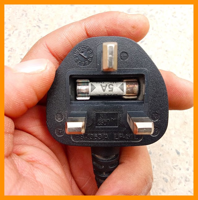
- The cheapest and available most step is using a three-phase input power cable. Using a three-phase power cable can prevent power surges. A three-phase power cable has a power fuse made of metal and glass to allow the specific voltages for which it is designed. When the power crosses the limits, the fuse burns itself and breaks the connection but it prevents the dangerous damage of power surges.
| PSU | UPS | Circuit Breaker | Power Cable |
|---|
 |  |  |  |
| Copatibility & Connection Checking |
|---|
- Compatibility defines the likeliness or similarity of a component. It is important to measure it. If a component supposes that a power supply is not compatible, there is a risk of high load on the motherboard leading to total damage. Compatibility prevents the bottleneck which is a hurdle in the performance of a system. As one purchases non-compatible components, it will be a total waste of money along with the risk of damage.
- A loose connection leads to an insufficient power supply to the connections. It can also cause bottle next. Mostly, loose connections lead to power cuts in systems. Locking cables can help to form a strong connection. Their use leads to satisfactory bond formation between connections. Therefore, it is important to check the connections.
| BIOS Update and Humidity Issues |
|---|
- There are certain risks associated with the BIOS of the motherboard as during booting of the motherboard any accidental power cut occurs then the system becomes fully unable to start because the motherboard has lost its BIOS system which provides this is to the windows. Moreover, there may also be a risk of incompatibility issues such that the new version of BIOS may not be completely friendly with the motherboard and may cause complexes to performance. There is also a risk of faulty BIOS updates that could introduce new security vulnerabilities to the system if not properly tested. It may raise certain security issues and can lead to the attack of malware and viruses. These are some risks related to BIOS updates. But, in more cases, s BIOS update remains useful.
- Humidity only occurs when a computer system is placed in an incompatible environment where re air humidity level is higher. Generally, shaded places have higher levels of humidity in the air. Humidity can lead to high moisture levels moisture that can cause oxidation and rusting of metallic parts such as circuit board connector ports and CPU add power supply units. These parts may face corrosion effects and corrosion leads to hardware failure of components. Moreover, humidity can lead to shortcircuitst in a motherboard causing electrical shortages and leading to the burning out of smaller chips. Overheating issues may also occur indirectly due to humidity because humidity affects the functioning of the cooling system and indirectly it may raise heating. These are the side effects caused by humidity in a motherboard.
| Practice of Cleaning & Dusting |
|---|
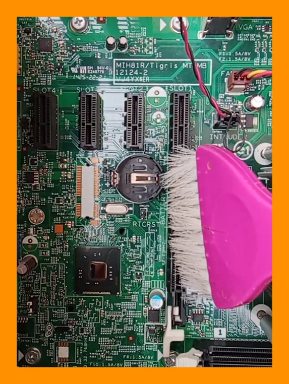
- Cleaning or dusting of the motherboard requires care and safety of components. Two secure and careful methods to clean motherboards including blower air and using a soft brush are given.
| Using Blower | Through Brush |
|---|
 |  |
- Proper cable management is an important step to overcome heat and sparking. Each motherboard case has certain spaces to set the cables. Spaces in my motherboard case are in the below gifs.
%20(1).gif)
| Preventive Measures Against Surges |
|---|
| Step 1 | Step 2 |
|---|
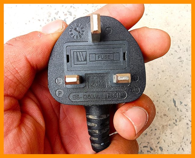 |  |
| Step one includes using a 3-phase power cable. I mentioned it at the first number as it is the cheapest and the safest among all methods. This cable is about 20-30% more expensive than the normal cable. Still, it can provide resistance when the spike ranges above 5 Amperes. | At least using an 80 PLUS Bronze power supply is necessary for safe computing. The PSUs with less than this credibility should not be used. Its mention on the second number is necessary as it holds the whole motherboard's power. |
| Step 3 | Step 4 |
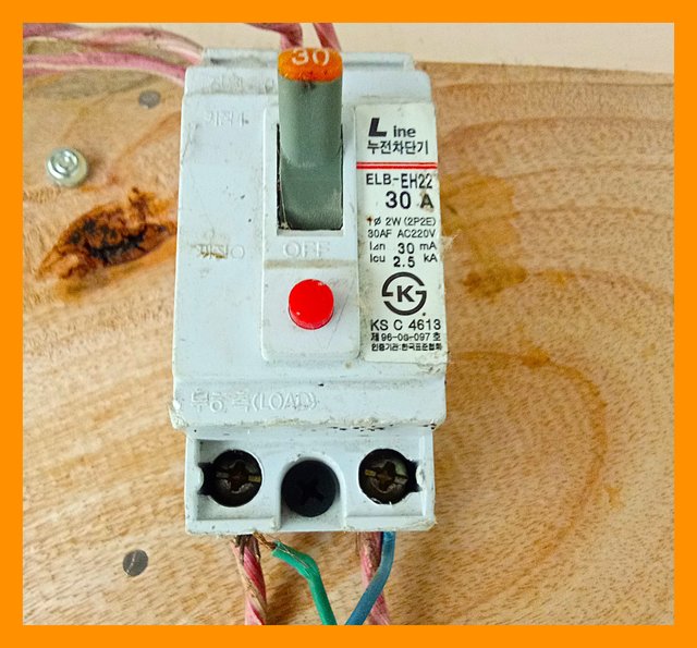 | |
| Using a circuit breaker helps to overcome spikes | UPS is expensive but its use makes 100% spike proof to circuits |
In the
@kouba01 sir for indicating my mistakes in the previous contest. I tried to improve in this contest. This contest has been prolonged using excessive images but I hope it will be useful for all visitors.


_20250224_120202.jpg)


%20(1).gif)


@tipu curate
Upvoted 👌 (Mana: 5/7) Get profit votes with @tipU :)