Arduino Remote Home #4
Hi and welcome back! A short post this time, just to follow through.
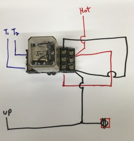
Near the end of the video about wiring switches I said I would find my drawing on how to turn a double pole double throw ice cube relay into a 4way switch. As I went through the folder of drawings, I also found one that might be of interest. The first pic here is a direct interpretation using the same formatting from the video. The jumpers I drew in the video, were completely wrong. The correct jumpers are designated by the red and black square shaped lines.

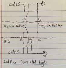
A quick aside, after looking through my drawings I realized that, although similar in function, each switching application may be wired a little differently (one size does NOT fit all). The next pic shows the most interesting and of all. How this works is not obvious, so I would like a minute to explain.
First off the two squiggly horizontal lines represent the division of the floors, ie: above the upper line shows 2nd fl. switch, in-between the two lines represents the 1st fl. switch and below the lower line represents the ice cube relay in the basement. The vertical lines that cross the squiggly lines, represent the actual wires running in the walls. Also on the drawing, there is a label at the bottom for future referencing. In the middle are two notes, “rag wire red tape” and “rag wire blk tape”. Those used to be T1 & T2, between 1st and 2nd floors. Now “rag wire red tape” is connected to the common terminals of the three-way switches, making it the only traveller, T1. And “rag wire blk tape” has become the S/L, both up at the light and down at the receptacle for the USB power supply. Rag wire is a term used to describe the insulation of older wire. Back in the day, a wires insulation had this cloth-like outer layer that over time degraded into a shredding fabric, a rag. At the top and bottom you see the “ circ #25” labels, indicating a hot at both ends. Now would be a good time to say that it is absolutely essential for the hot at both ends to be the SAME hot, ie:same circuit. The last bit of information is just below the lower squiggly line, 12-3 (space) rd (space) wh (space) bk. Indicating I was able to install a new romex from the 1st floor switch down to the control relay. Not included here is how the switches were before I monkeyed with them.
Finally in the video demonstrating how the web page functioned, I came across a bug with the “Back Yard Lights”. Turns out it wasn’t a bug at all. Rather, it was the result of me not being carful when removing/installing the SD card from the ethernet shield. Apparently I jiggled the header connector at the end of the Mega ever so slightly. But enough to break the connection between the Mega and the output board on that pin only. It took less than five minutes to find. A pay off directly attributed to “knowing” the system. Again I say, build it yourself, you’ll be glad you did.