Arduino Remote Home #3
Before going on, I need to make a correction. I said that the output reed relays have 5v coils and were switching 5v, that was incorrect. They are actually switching 12vdc.
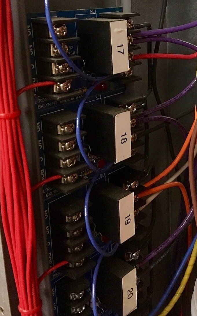
The next H.A.S. component is the tall wiring trough. There are several conduits that enter at the top, each with as many as eight #12 awg conductors. These come from switch boxes through out the basement and first floor. There is also a 3/4” conduit from the electrical panel. There are a boat load of wires in there, and I must say it looks intimidating seeing them all at once. But I added them, in small groups, taking detailed notes and making little sketches. There are twenty-five Altronix rb5 relay modules  with contact ratings of 5amps @120vac. There are two ice-cube relays, that send the garage door opener signals. Then back to the circuit board box, I put eight ice-cube relays rated for 20amps @120vac behind the white steel plate. Giving a total of thirty-five control relays. I need to go into some electrical wiring ideas to explain exactly how I connected all those wires to the relays.
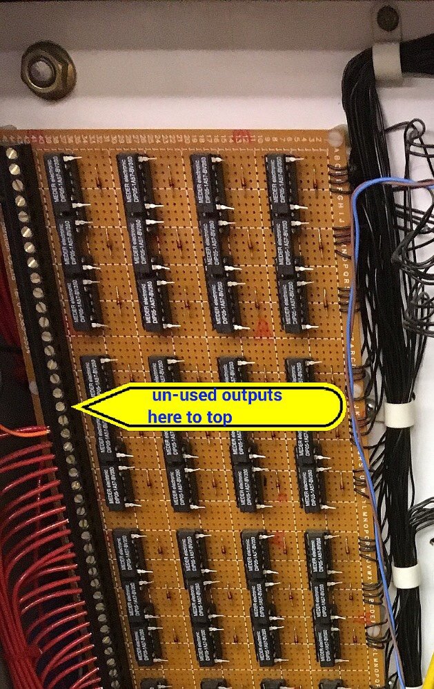
I’m still deciding on how to use the remaining outputs.

I’m pretty sure I’m going to control the pump that circulates the hot water loop. And I’m considering hacking into my heating and air system as well. While I’m on that subject, the wifi thermostat “Nest”, at first glance appears pretty cool. But after some careful mental dissection , I come to the conclusion that it is not for me. I don’t get what it has over a good 7 day programmable stat that is properly set up. I’m also considering using some of the outputs to control pumps and valves on a solar water heating system. Those ideas will be implemented in future phases.
I hope that makes sense of the output control and input monitoring. Feel free to ask questions and I’ll do my best to respond in a timely manner.
Before finishing this post, I want to show you a screen capture video of the web page and its use.