Understanding Transient Analysis with Scilab

| Intended Learning Objectives |
|---|
| At the end of the tutorial, readers should be able to learn how to: 1. determine the step response of a series RLC circuit; 2. perform the transient analysis on a series RLC using Scilab; 3. Plot the step response of a series RLC circuit using Scilab. |
| II. Requirements |
|---|
 (image credited to scilab.org)To be able to follow the discussion and tutorial, readers should have a desktop PC or laptop ( Windows 7, 8, or 10) and an installed a latest Scilab (an open source high level numerical analysis and programing) app either 32 or 64 bit that can be downloaded at scilab.org. |
| III. Difficulty |
|---|
| Advance |
| IV. Introduction |
|---|
| In AC circuit analysis, passive component behavior can be characterized in two state: transient and steady-state. The rapid changes in the current and voltage level in each component at the moment you turn on a switch on a fully functional circuit that contains resistors, inductors, capacitors and, power sources is called the transient response. The transient response is the natural response of the circuit when a sudden inrush of current or voltage flow through out the circuit component until parameters normalize. The equilibrium state, on the other hand, is called a steady-state response , where current and voltage values in the circuit is normalize. For this tutorial, i will explain how to perform transient analysis on a series RLC to determine the step response of the circuit. The numerical analysis is carried out through writing a program in Scilab that enables us to plot the step response of a series RLC circuit. In addition, in this analysis, we would be dealing with differential equation that would represent the energy-storage elements. |
| V. Step Response of series RLC circuit |
|---|
We consider the series RLC circuit in figure 1. The step response is observe when you suddenly turn on and off the switch in the circuit. Step response signifies the transient state of the circuit where the natural behavior can be observe by repeatedly change from t =0 to t > 0. Figure 1: Series RLC circuitApply KVL (Kirchhoff's Voltage Law) around the loop for t >0. Kirchhoff's Voltage Law states that the sum of all voltage inside a closed loop is equal to zero. So, we obtain the following equation:  Figure 2: Applying KVL andFrom figure2, the equation derives from the inductor is a factor of the inductors' self inductance and of the derive of current (i) with respect to time (t). So, we have the equavalent equation at inductor as L di/dt . The current passing through the circuit could be represented as the relationship with the circuit connected capacitance and voltage. The current across the circuit (i) is equal to C dv/dt. Substituting the current (i) as a factor of capacitance and voltage, we have the following equation:  Simplying the equation derive above, we will consider a two state in our analysis which is the transient and steady-state.  Transient response  is the component where the total response dies out with time. The transient response of a circuit is either overdamped, underdamned, and critically-damped which is defined by the following equations below. is the component where the total response dies out with time. The transient response of a circuit is either overdamped, underdamned, and critically-damped which is defined by the following equations below.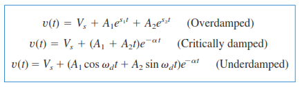 To explain the different transient response of a series RLC circuit, we will use the circuit shown in figure 3, we will find v(t) and i(t) for t > 0 by considering three cases: R = 5 ohms, R = 4 ohms, and R = 1 ohms.  Figure 3: Example Circuit |
| VI. Transient Analysis with Scilab Implementation |
|---|
We will create a Scilab program that will allow us to easily change values of R using the input('statement'); function. Then, write the a program to implement the steps in conducting transient analysis. Now, we write a code that enables to accept values of R, L, and C. R1=input('Enter value of R1 in ohms:'); R2=input('Enter value of R2 in ohms:'); L=input('Enter value of L in Henry:');C=input('Enter value of C in Farad:'); Vs=input('Enter value of source voltage (Vs) in volts');In determining the circuit's transient response, we need to determine the initial values of current (Io) and voltage (Vo). Io is equal to the current experience between all connected resistor as to the voltage (Vs ) applied to the circuit, while Vo is the voltage across R2 when switch is flipped at t>0. So we write the code as: Io = Vs/(R1+R2); //initial current valueVo = R2(Io); //initial voltage valueNext, we will determine the transient condition of the circuit either it is overdamped, underdamped, or critically-damped. We will determine characteristic root a =  and w0 = and w0 =  for t > 0. Take note that the value to be used in the equation stated earlier ar R1, L, and C. To be able to take the square root of a function or a number, use the for t > 0. Take note that the value to be used in the equation stated earlier ar R1, L, and C. To be able to take the square root of a function or a number, use the sqrt() in Scilab. The following conditions will determine the transient response of the circuit: 1. when a > w0, the circuit is overdamped; 2. when a < w0, the circuit is underdamped; and, 3. when a = w0, the circuit is critically damped. We start by solving the value of a and w0. a=R1/(2*L); // coefficient aw0=1/sqrt(L*C); //coefficient w0 Using if and elseif function, we will create a program that will implement the conditions stated earlier. Inside the if() and elseif() function, we will have the different mathematical operations and analysis for each of the condition stated. We will also use the equation derive in the the prior section of this text. Case 1: When R = 5 ohms. For t < 0, the switch is closed for a long time by which capacitors behaves like open circuit while inductor acts like a short circuit. For case1, we initialize a condition for overdamped response of the circuit which is characterize by a > w0. Inside the if function, we will implement the derive equation for overdamped response and the derivative of this equation. To be able to solve the value of v(t), we need to manipulate the equations to solve for A1 and A2. However, it will become more complicated if we try to use subtitution or elimination technique in our program implementation. So, we will use the matrix functionality to solve the values for A1 and A2. So, we write the code as: if(a>w0) then t=0;//Matrix operation to find A1 and A2constV=[(Vo-Vs), Io/C];coefA=[exp(s1*t),exp(s2*t);s1*exp(s1*t),s2*exp(s2*t)];A=inv(coefA)*constV(:); Next, we include a code. The program above is derive from this simplified matrix taken from the equation stated earlier.  To finalize all operation for case 1, we will need to implement a code that will allow as to plot v(t) as a function of time as 0 < t < 10 sec with plot step of 0.1. disp(A);t=[0,0.1:10];Vt=Vs+ A(1)*exp(s1*t)+A(2)*exp(s2*t);disp('V(t)=');disp(Vt(:));plot(t,Vt);Case 2: When R = 4 ohms. For t < 0, the switch is closed for a long time by which capacitors behaves like open circuit while inductor acts like a short circuit. For case2, we initialize a condition for critically-damped response of the circuit which is characterize by a = w0. We will continue by using elseif() function.//When a = w0 ,the circuit is critically-damped responseelseif(a==w0) thent=0;//Matrix operation to find A1 and A2constV=[(Vo-Vs), Io/C];coefA=[exp(-a*t),(t*exp(-a*t));(-a*exp(-a*t)),1];A=inv(coefA)*constV(:);  This time the matrix of equation that we will be manipulating in the code is shown above. Instead of using s1 and s2, we will using the characteristic root a hence at critically-damped response, the circuit is in resonance. Next, we will plot and display the value of v(t) at a t is equal to 0 < t <10. disp(A); t=[0,0.05:10];Vt=Vs+A(1)*exp(-a*t)+A(2)*t*(exp(-a*t)(:));disp('V(t)=');disp(Vt(:));plot(t,Vt);For the voltage Vt=Vs+A(1)*exp(-a*t)+A(2)*t*(exp(-a*t)(:)); plot equation, directly multiplying matrix with different number of rows and columns results to an error so you need to determine when to transpose the matrix. For instance, multiplying A(2)*t results to 1x10 matrix which could not be multiplied directly to an identical 1x10 matrix at the result of exp(-a*t). So, we need to transpose the last part of the equation: (exp(-a*t)(:). Case 3: We will still be using the same circuit but now will consider R = 1 ohms in building our program. For case 3, we will identify the underdamped response of the circuit that will satisfy a < w0. //When a > w0 ,the circuit is underdamped response elseif(a<w0) thent=0;//Matrix operation to find A1 and A2wd=imag(s2); constV=[(Vo-Vs), Io/C];coefA=[cos(wd*t)*exp(-a*t),t*sin(wd*t)*exp(-a*t); exp(-a*t)*wd*sin(wd*t),exp(-a*t)*wd*cos(wd*t)];A=inv(coefA)*constV(:); sin() and cos(). In addition, since the underdamped response of a circuit involves the complex properties of the circuit response, we also use imag() to call out the imaginary properties of the characteristic root a. Then, we write a code to display and plot the underdamped response as a function Vt at t < 10. disp(A);t=[0,0.1:10]; Vt=Vs+A(1)*cos(wd*t)*exp(-a*t)(:)+A(2)*t*sin(wd*t)(:)*exp(-a*t);disp('V(t)=');disp(Vt(:));plot(t,Vt);endIn addition, we will also use matrix transpose to be able to perform multiplication of matrix which i have discuss earlier in case 2. Here is the code in the SciNotes.  |
| VII. Running the code in Scilab Console | |||||||||
|---|---|---|---|---|---|---|---|---|---|
| We will need to run thr code from the SciNotes to the Scilab Console by clicking the simulation button. Case 1:(Overdamped Response) Input values of R1 = 5 ohms, R2= 1 ohms, L = 1 Henry, C = 0.25 Farad and Vs = 24 V. In this condition, the circuit components does not oscillate as it returns to steady-state. So, we can see in the resulting plot that there is an exponential decay of v(t) value as it approaches steady-state (t > 10).   Case 2:(Critically-damped Response) Input values of R1 =4 ohms, R2= 1 ohms, L = 1 Henry, C = 0.25 Farad and Vs = 24 V. The plot shows a quick and rapid changes in v(t) as it approaches steady-state without oscillation.   Case 3:(Underdamped Response) Input values of R1 =1 ohms, R2= 1 ohms, L = 1 Henry, C = 0.25 Farad and Vs = 24 V. We can see in the plot a gradually decreasing amplitude of oscillation that approaches to zero. 
After inputting all the values and Vt values are displayed, a critically-damped response plot shows in the Scilab graphical window. | 
Posted on Utopian.io - Rewarding Open Source Contributors |

Congratulations! This post has been upvoted by the communal account, @steemph.cebu by juecoree being run at Teenvestors Cebu (Road to Financial Freedom Channel). This service is exclusive to Steemians following the Steemph.cebu trail at Steemauto. Thank you for following Steemph.cebu curation trail!
Don't forget to join Steem PH Discord Server, our Discord Server for Philippines.
Thanks for sharing your learnings... We never done that before😣 Performing such activity will help students to understand more behind its behavior. Through experiments and tests, students will broad their knowledge in a certain topic😊
Hi @dapmonylia ! I am glad it helps you. Yes, hand-on activities is very essential in learning basic and advance circuit theory. Appreciated! Cheers!
Thank you for the contribution. It has been approved.
You can contact us on Discord.
[utopian-moderator]
Thanks @laxam
Hey @juecoree I am @utopian-io. I have just upvoted you!
Achievements
Community-Driven Witness!
I am the first and only Steem Community-Driven Witness. Participate on Discord. Lets GROW TOGETHER!
Up-vote this comment to grow my power and help Open Source contributions like this one. Want to chat? Join me on Discord https://discord.gg/Pc8HG9x