Share My Technical Skills ( Metal Detector Circuit Diagram)
| Greetings, love & respect to all of my steemian friends |
|---|
| Assalamu Alaikum |
|---|
I am @saifuddinmahmud from Bangladesh. There is a beautiful and amazing contest organised by @mahadisalim. The name of the contest is "share your technical skill". I am going to share my skill. I hope everyone will like my post.

Today I will show you a metal detector circuit diagram. These metal detectors are widely used, especially in various types of factories, parking area and any kind of metallic signal.
These are the instruments I need to build this circuit.

- SMPS ( Switched Mode Power Supply 220/24 VDC)
- Relay with socket ( 24 VDC)
- Proximity sensor (PNP)
- Indicator lamp
- 2 pin plug
- Combined socket/ circuit breaker
All the equipment I need to do this work.

- Multimeter ( For testing voltage)
- Tester
- Cutting players
- Pieces of cable

First, I connected 220 lines to the combined socket. I took the output from the output pin of the combined socket through a 2-pin plug. I took the red wire as positive and the yellow wire as negative.

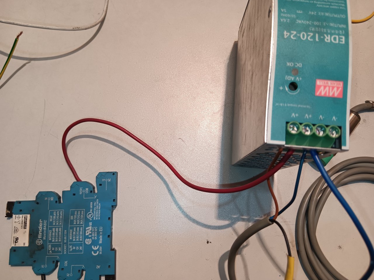
There are 3 inputs at the input of SMPS. Among them, L is the phase line or positive input, N is the neutral or negative line input and the other is the earthing. I connected the red wire to the positive input and the yellow wire to the negative input.

I checked if the voltage was connected properly with a voltmeter. It shows above 220. That means I have the correct voltage supply.

Since I need 24 volts at the output, I checked whether the output voltage is correct. It shows 24 volts here. That means my output voltage is properly supplied.

The three wires of a proximity sensor typically serve as power supply, ground/ neutral and output signal wires. The brown wire of the sensor is positive. So I connected the brown wire to the positive + pin. I connected the blue wire to the negative - pin. This way the sensor got the voltage supply.

I connected the black wire of the sensor, which is the output signal, to the A1 pin of the relay. I shorted another wire from the negative v- pin and connected it to the A2 pin of the relay.
I connected a red wire from the + positive pin of the SMPS to the pin marked com/11+13 of the relay.

I took a wire out from the pin marked NO 14 of the relay. I connected this wire to the positive end of the indicator lamp.

I connected a wire from the negative v-pin of the SMPS to the negative end of the indicator lamp.

My circuit is complete. You can see that the indicator lamp is now off. When I bring any metal sensor into contact with it, the indicator lamp will light up.
As soon as I brought the metal part of the tester into contact with the sensor, the indicator lamp lit up. When I removed it again, the indicator lamp went off. You can also use a calling bell here instead of the indicator lamp.
| What is SMPS |
|---|

SMPS full meaning is switched mode power supply. It is an electronic device that regulates voltage. If 220 volts are supplied at the input, the output can be low voltage or voltage of different values. It converts ac voltage to dc voltage.
| What is Proximity Sensor |
|---|

A proximity sensor is a type of sensor that can detect nearby objects without any contact. It can indicate the proximity of an object without touching it. Proximity sensors can be of different types, such as infrared, ultrasonic, capacitive, and inductive proximity sensors.
| What is Relay Socket |
|---|

This is a relay socket. For installing relay modules, so that it can easily take input and output from PLC or other control circuits.
| Here is my YouTube link |
|---|
Thanks to my dear steemian friends Who read my post.
| My invitation friends |
|---|
@mdpolasmia
@rafi67
@nurnobi10

X promotion link
https://x.com/uddinsaif208/status/1948712098034323460?t=hzh6R0Cs4t40F5RAbDtVng&s=19