Contest || Share Your Technical Skill
| Assalamu Alaikum |
|---|
I am @saifuddinmahmud from Bangladesh. I am excited to join this contest. The contest name is share your technical skill. The contest organised by honorable @mahadisalim. I am going to join this contest. I hope everyone will like my post.
Edited by Canva
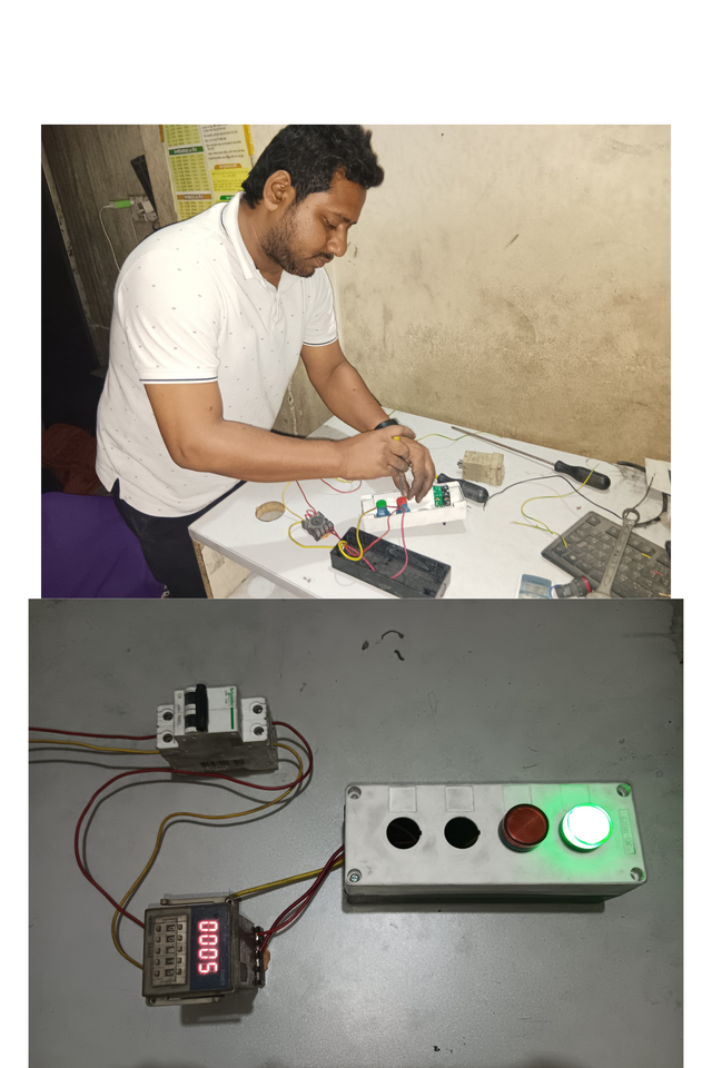
Anyone can benefit from the project I did today. I controlled 2 lights on and off with a timer. However, there are many more things that can be done with this project.
Imagine you have a water tank in your home. It takes 30 minutes to fill that water tank completely. If you set a timer for 30 minutes, the water motor will automatically turn off after the tank is full.
If you want, you can turn the air conditioner on and off or any other electronic or electrical device on and off according to your schedule.
Some of the things I need for this job are:
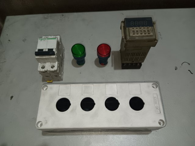
- Miniature circuit breaker (MCB 2A,6A or according to the load)
- Indicator lamp ( 2pcs)
- Control box
- Timer.
- Voltage supply 220V/110V/24V according to your load.
My instruments which need in work time.
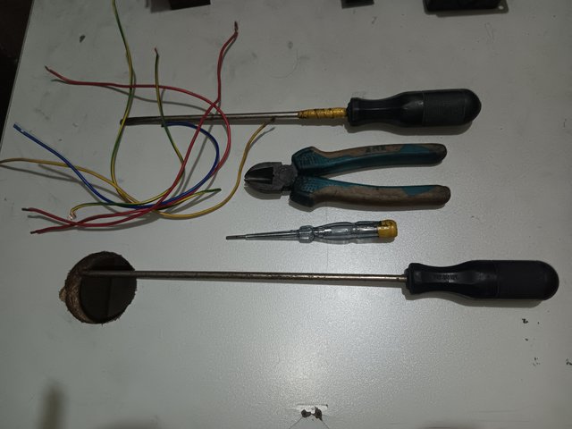
- Small pieces of Cables.
- Star screw driver.
- Flat screw driver.
- Tester.
- Cutting players.
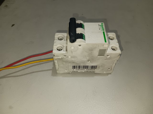
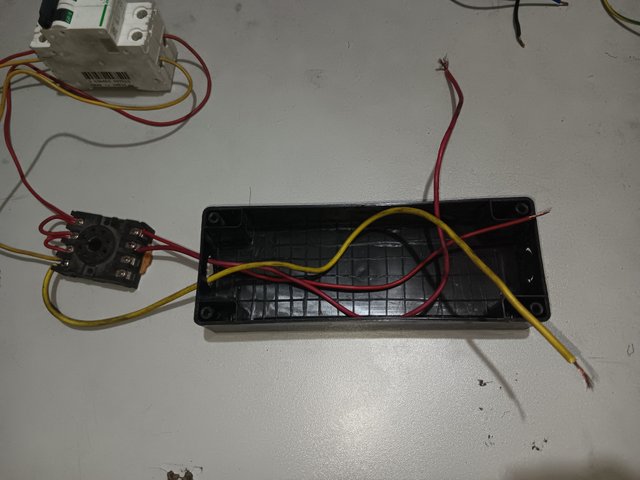
I have taken a 6 ampere circuit breaker for my work. I have connected two wires to provide 220 supply voltage to the input line of the circuit. Out of which the red wire is the phase and the yellow wire is the neutral.
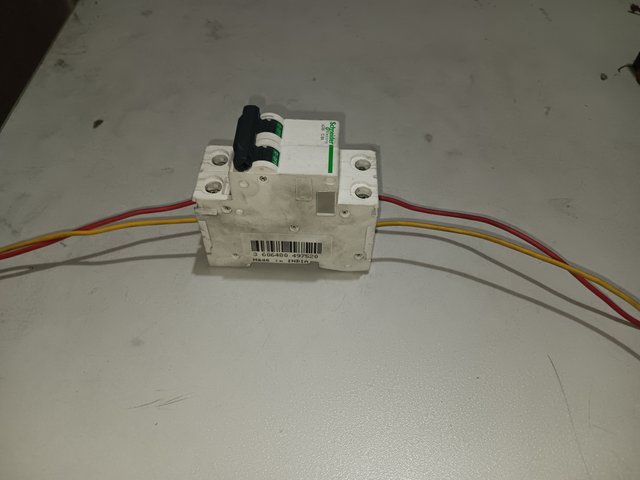
We will connect a red wire and a yellow wire from the output, with the red wire being the phase wire and the yellow wire being the neutral wire.
 |  |
|---|
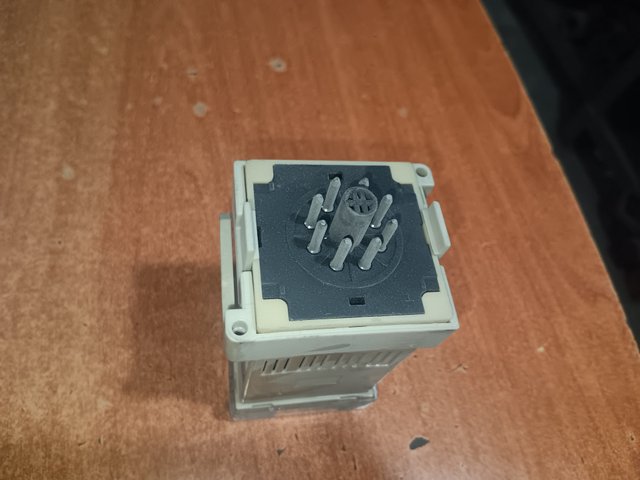
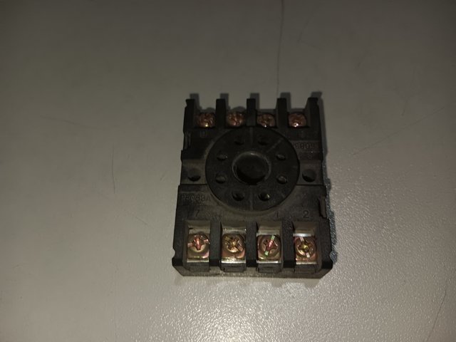
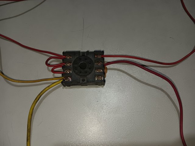
I will take an 8 pin timer to make my circuit. I will make my connections based on this timer. There are 8 holes numbered 1-8 where the positions of the timer will be connected.
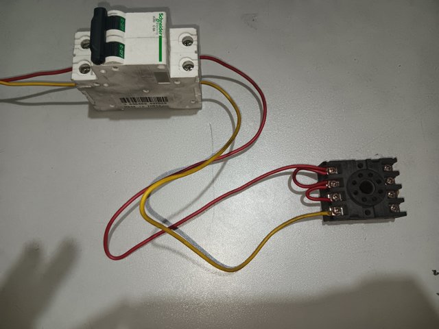
I will now connect the base of the timer. I will connect the phase line to pins 7,8,1 of the timer. I will connect the main phase to pin 7. From this, I will connect it in a loop to pins 8 and 1, so that the phase line will reach my pins 8 and 1. I also connect the neutral wire to the pin no 2.
 |  |
|---|
I will take two phase outputs from pins 5 and 6 of the timer. 5 no pin works as NC(normally closed) and 6 is NO(normally open). I will take a yellow wire from pin 1 of the timer base and attach it to the other end of the indicator, which will act as a neutral.
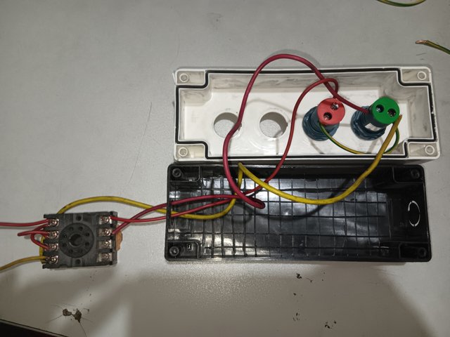
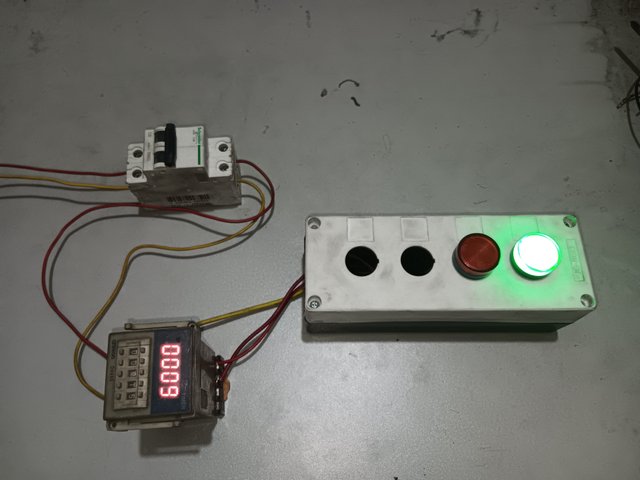
I will connect a wire from pin 5 to the green light. This way, when I apply power to the circuit, the green light will light up.
When I want to turn on any motor or device in place of this green light, it will remain on.
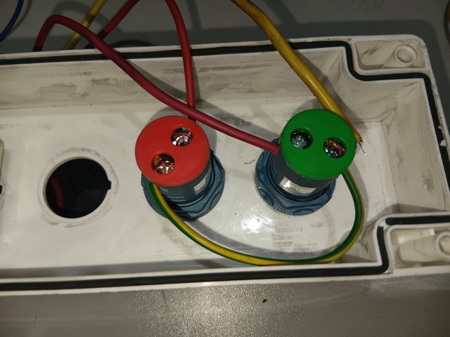
I will take a small wire from one indicator in the form of a loop and attach it to the other indicator, so that my other indicator will have a neutral connection.
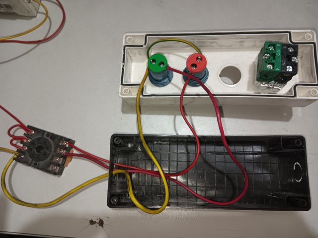
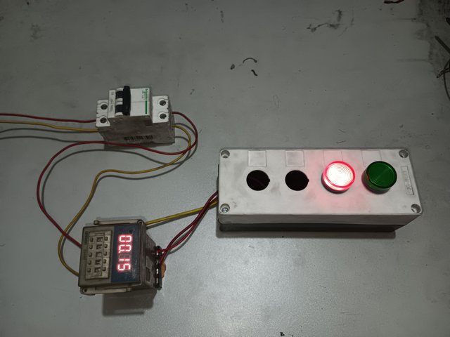
I will connect another wire from the pin no of 6 to the red indicator lamp.
I will set the time on the timer. The red light will come on after the time I set. Imagine I set the time to 10 or 15 seconds and the red light will come on after that time.
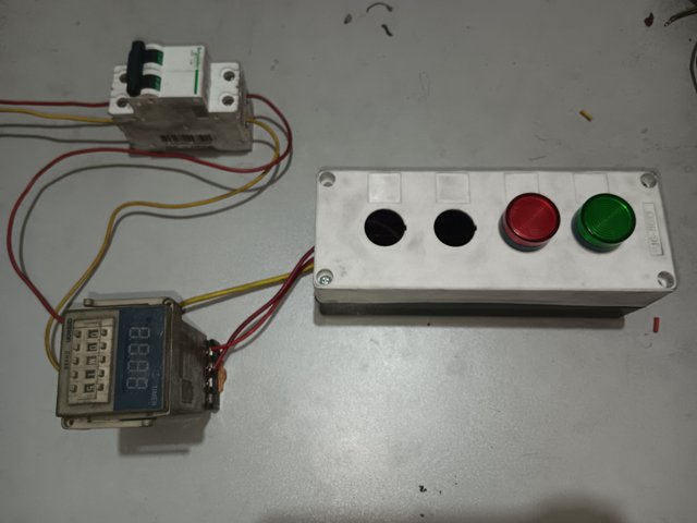
I placed the indicator lamps in a control box to make it look nice and easy to use.
 |  |
|---|
I turned on the breaker. I set my timer for 15 seconds. When I turned on the breaker, the green light came on, and 15 seconds later the red light came on.
| YouTube link |
|---|
Thanks to everyone who read my post
My invitation friends
@rafi67
@azad45
@shihabuddin48

X promotion link
https://x.com/uddinsaif208/status/1920844272388981093?t=-l16mJWVjxt_3oFLHp1rsQ&s=19