Electrical Tutorial || What is Circuit, Series circuit & Parallel Circuit.
| Hello my dear steemian friends, Assalamu Alaikum |
|---|
I am @saifuddinmahmud from Bangladesh. By profession i am an electrical engineer. I have enough experience about electrical instruments. Today i am going to share some interesting things about electricity.

Edited by Canva
| Topic: | Circuit | Series circuit | Parallel circuit |
|---|
I shared about current, voltage and resistance in the previous post. But the question may arise in our mind that how this current is transmitted. When we press the switch, the fan light or any electrical instrument turns on. Sometimes when we press a switch, multiple lights turn on. Sometimes multiple switches are needed for multiple lights. Today, I will show you in this tutorial how these circuits are made.
A circuit is a closed path through which current flows.
| Example |
|---|

There is a load at the end of this circuit. I need a path to turn on this load. When I switch on the load, the path through which the current and voltage reach the load is called a circuit.
According to situation the Circuits are generally of two types.
- Open circuit
- Close circuit
- Open Circuit
When any part of a circuit is open or disconnected, due to which electricity cannot flow, it is called an open circuit.
| Example |
|---|
- Circuit Diagram

You can see that the switch in disconnect position where one end of the conductive wire is separated from the other end, due to current is not flowing. For that the light is in off position. This is called an open circuit.
- Practical

I have taken the socket as the voltage source. The output of the circuit breaker has gone to the line to the light. The breaker is now in the off position, so the light is not on. Because the breaker is now in the off position, it has left the circuit open.
- Close Circuit
When a circuit is complete and electricity can easily flow through it, it is called a closed circuit.
| Example |
|---|
- Circuit Diagram
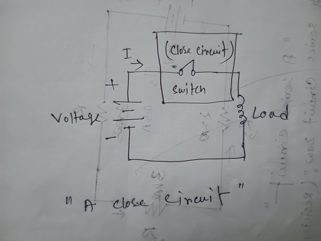
You can see that the switch in connect position where one end of the conductive wire is connected to the other end, due to current is flowing easily. The light is on. This is called an close circuit.
- Practical

I have taken the socket as the voltage source. The output of the circuit breaker has gone to the line to the light. The breaker is now in the on position, so the light is on. Because the breaker is now in the on position, it has closed the circuit.
According to structure the Circuit are generally two types :
- Series circuit
- Parallel circuit
When there is only one path for current to flow in a circuit, we call it a series circuit. In a series circuit, the current remains the same but the voltage is divided.
| Example |
|---|
- Circuit Diagram

There is only one current flow path for multiple loads. There are 2 lights in total where there is only one path for current flow to turn on the lights.
- Practical-01

Here a red cable has been connected for the current flow from the output of the breaker because there is only one path for the current flow in the series line. You can see that the breaker is in the off position so the lights are also off. I have used one breaker for 2 lights because 2 lights will be lit from one breaker.
- Practical-02

As you can see, I have now turned the breaker to the on position. As a result, the two lights are on at the same time. I have used one breaker for the two lights. Because two lights will be lit from one breaker. The current flows through one path and turns on both lights.
- Practical-03

Here the supply voltage of the first light is shown as 234.
- Practical-04

Here the supply voltage of the second light is shown as 113. This is because the voltage is divided in a series circuit.
When a circuit has more than one path for current to flow, we call it a parallel circuit. In a parallel circuit, the voltage remains the same but the current is divided.
| Example |
|---|
- Circuit Diagram
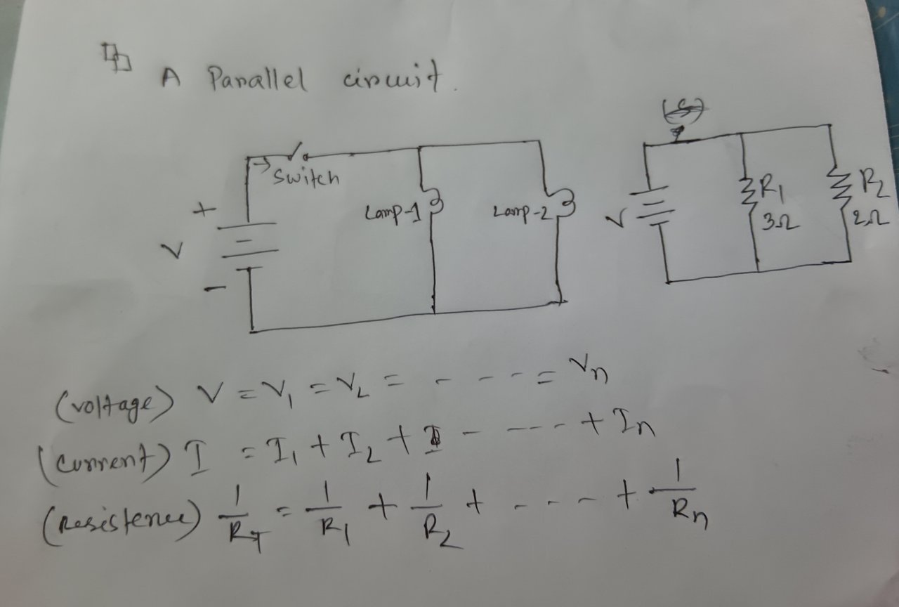
You can see in the circuit that the source is a current flowing line that has split into different paths. Two separate lights have been connected to turn them on and off. This is a parallel circuit.
- Practical-01

Here, a line enters the input from the source to the feeder, divides, and enters multiple feeders. It is connected to multiple lights through the output. That is, multiple paths for current flow are created according to the rules of parallel circuits. Now both lights in off position.
- Practical-02

In this situation, when I turn on a breaker, the first light will come on and the other light will be off.
- Practical-03

In this situation, when I turn on the second breaker, one light will come on and the first light will remain off.
- Practical-04

If I want, I can turn on two breakers at the same time and keep them on, and I can turn off the lights by turning off two breakers at the same time. That is, I can turn on any one light according to my needs and turn off the other light, and I can turn them on and off simultaneously.
- Practical-05

Here the voltage of the first light is showing 237.
- Practical-06

Here the voltage of the second light is showing 237. Because the voltage remains the same in a parallel circuit.
| Differences between series & parallel circuit |
|---|
| Series | Parallel |
|---|---|
| |
| There is one path for current to flow | There are multiple paths for current to flow |
| The voltage is divided | The voltage remains the same |
| The current remains the same | The current is divided |
Thanks to my dear steemian friends Who read my post.

Thank you very much for sharing such a nice tutorial post about series and parallel. Here you have shown two lights on and off with two circuit breakers which were connected in parallel. And in another connection you have shown two lights in series with one circuit breaker. Now my question is how many 60 watt lights can be run in series with 220 volt input voltage. I don't think more than two lights can be run in series with 220 volt input voltage. If three or four lights have to be lit in series then 440 volts will have to be applied, probably it is for the series line.
Thank you very much for reading my post. Actually 220 volts and 440 volts are completely different. You have to select the voltage supply depending on the load. If you give 440 volts supply instead of 220 supply, then the circuit will burn out or any accident may happen. This idea that you have to increase the voltage or give 440 volts supply to light multiple lights is wrong. If you want to light 3,4 bulbs in series, then you have to take high wattage lights. Remember that if you want to light 3,4 lights, then you have to use high wattage lights. I use here 200W light. Since the voltage is divided in series, the light of lights 3,4 will be very low and may not light in many cases. For this, you have to connect in a parallel circuit to light multiple lights.
A high-wattage bulb will produce some light even at low voltage. But a low-wattage bulb at low voltage is more likely to produce no light.
Thank you for your answer. As far as we all know, in parallel connection, all loads get the same voltage and this is the most practical way to light multiple lights. So if we connect four lights in series, each light will receive only 55V, so it will not light up or will give very little light. Thanks for your explanation, but one thing needs to be clarified here, is the wattage or voltage of the light important in series connection. If the sum of the rated voltage of each light is equal to the supply voltage, then I think all the lights will light up properly. So I think the real issue is not high wattage, but selecting the right voltage light.
Imran bro, if you supply 440 volt source voltage, you will have to install 440 volt lights. If you make series or parallel connections here, then 220 volts, you will have to install 220 volt lights. At 220 volts, you will get a two-wire connection. If you provide 440 volts, you will have to provide a three-phase connection. Is it possible to provide three-phase connection to the lights? I hope you understand.
I understood from the previous answer that multiple lights can be operated in parallel connection and multiple lights cannot be operated in series connection. The light may be dim or may not light up at all.
You are correct, if you connect 420 volts to light the lights, you need a three-phase line because there are no three-phase lights. So if you connect lights in series at 220 volts, it is probably not possible to run more than 2. The light will be dim or not light at all.