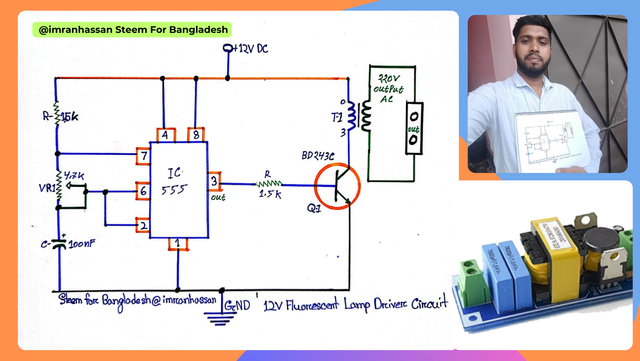
How are you all, friends? I hope you are well; I am also well. In today's post, I will show you the process of making a 12V fluorescent lamp driver circuit.
.png)
Edited with Canva.
In today's circuit diagram I will show you how to generate 230V AC output from 12V DC input using an NE555 Timer IC. This circuit uses a MOSFET and transformer, which converts our low-voltage DC power into high-voltage AC power. And the main function of our circuit today will be to run the equipment which is powered by 230V.
| Components used and their functions |
|---|
Timer IC (NE555):
Edited with Canva.
It does the timing and signal control of the circuit.
Potentiometer (4.7K):
It is a variable resistor, with the help of which the input signal of the circuit can be controlled.
DC 12V:
The circuit requires a 12V DC power supply to work.
Resistors (1.5K):
These resistors control the signal and limit the current flowing in the circuit.
Step-up Transformer:
This transformer converts the 12V DC input signal to 230V AC output.
Power Transistor (BD243C):
It is a power transistor which amplifies the signal received from the IC and is used to supply power to the transformer.
Capacitor (100nF):
The capacitor helps in filtering the signal and holding the power in the circuit so that the signal remains stable.
| Now I am starting the step-by-step diagram drawing. |
|---|
| Step 1: NE555 Timer IC Pinout |
|---|
First I took the NE555 Timer IC and marked its pinouts correctly. Pin 1 Ground: Zero voltage of the IC. Pin 2 Trigger: Used to trigger the signal. Pin 3 Output: Provides the output signal. Pin 4 Reset: Used to reset or restart the IC. Pin 5 Control Voltage Input Pin: It helps in controlling the performance of the IC. Pin 6 Threshold Pin: Used for timing and signal control. Pin 7 Discharge: Pin used to discharge the charge of the capacitor. Pin 8 Power Supply: The power supply pin supplies voltage to the circuit.
| Step 2: NE555 IC Connection |
|---|
Then I connected pin 1 to ground and pin 8 to positive 12V. And also connected pin 4 to the positive line so that the IC does not reset and continues to work normally.
| Step 3: Resistance and Variable Resistance Connections |
|---|
In this step, I have connected the 1.5K resistor on the left side of the circuit to pin 7 of the IC. Then I have connected the VR 4.7K variable resistor to pin 2 and pin 6. In addition, I have connected the 100 nF capacitor between pin 2 and pin 1 as a control voltage. The timing configuration and functionality of the circuit will determine that.
| Step 4: Output Connection and Transistor Usage |
|---|
In this step, I have connected the 1.5K resistor to pin 3 (output) of the NE555 IC as a control line, which provides the correct voltage to the base of the transistor, and then I have connected the MOSFET (Q1: BD243C) transistor, which amplifies the signal. Then I connected the transformer (T1), which converts the output signal to 230V AC.
This 12V fluorescent lamp driver circuit is made using an NE555 timer IC, which is a simple and effective lamp driver circuit. It uses a transistor (BD243C) and a transformer to convert 12V DC input to 230V AC output. And as per the community guidelines, I took a selfie with my hand-drawn raygram and wrote my username and community name.
| S.no | Component | Value | Qty |
|---|
| 1 | Timer IC | NE555 | 1 |
| 2 | Potentiometer | 4.7K | 1 |
| 3 | DC | 12V | 1 |
| 4 | Resistors | 1.5K | 2 |
| 5 | Step-up Transformer | – | 1 |
| 6 | Power Transistor | BD243C | 1 |
| 7 | Capacitor | 100nF | 1 |
.gif)
🟩 Thank you for reading my post and giving your valuable time. Stay well and stay healthy. God bless you.
🟩 |
|---|
| Photography Details | 📱 Device: Walton Xanon90 | 📍 Location: Narayanganj, Bangladesh | 📷 Captured By: @imranhassan |
|---|


.png)
.gif)
https://x.com/ImranHosen98536/status/1943905140546970110
Thank you very much for sharing a beautiful article with us. Hope you stay active and keep engaging with everyone. Join our Discord servers for help. Click the link below to join our discord server. https://discord.gg/6by5BAtAAC