10 Minute Timer Circuit | Using 555 Timer IC.
Assalamualaikum Everyone. I am @imranhassan From #Bangladesh
.png)
| Materials used and their functions |
|---|
555 Timer IC:
 |
|---|
It is used for timing and signal control. This circuit is a very important component for setting the time of 10 minutes.
Resistors (R1, R2, R3):
 |
|---|
These resistors are used for voltage division and signal control, which helps in the timing configuration of the circuit.
Capacitors (C1, C2):
 |
|---|
These capacitors help in holding charge and managing the timing configuration.
** LED: Diodes (D1, D2):**
 |
|---|
A light source, which produces light by receiving electrical energy.
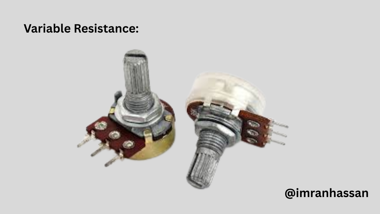
Potentiometer:
 |
|---|
A variable resistor, used to control a signal or voltage.
Switch (S1):
 |
|---|
It is used to start and stop the timer.
Battery (9V):
 |
|---|
Used to supply power to the circuit.
| Steps to make the circuit |
|---|
| Step 1: 555 Timer IC Connection |
|---|
 |
|---|
First, I took the 555 timer IC and marked its pinouts correctly and arranged them. Below is my interpretation of the pinouts:
Pin 1 Ground: Zero voltage of the IC.
Pin 2 Trigger: Used to trigger the signal.
Pin 3 Output: Provides the output signal.
Pin 4 Reset: Used to reset or restart the IC.
Pin 5 Control Voltage Input Pin: It helps in controlling the performance of the IC.
Pin 6 Threshold Pin: Used for timing and signal control.
Pin 7 Discharge: Pin used to discharge the capacitor charge.
Pin 8 Power Supply: Power supply pin, provides the voltage to the circuit.
Here are the pinouts of the 555 timer IC.
| Step 2: Resistance and Capacitor Connection. |
|---|
 |
|---|
In this step, I connected the 555 timer IC pinouts and connected the R1 (10 kΩ) resistor to pin 4 and the C1 (0.01 µF) capacitor to pin 5. Then, I powered the circuit with a 9V battery.
| Step 3: Resistance, Capacitor, Switch Connection |
|---|
 |
|---|
In this step, I connected the C2 (150 µF) capacitor to pin 7 (discharge). Then I connected pin 4 (reset) to pin 2 (trigger). Then I connected a switch to turn the circuit on/off.
| Step 4: Variable Resistance, Capacitor and Diode Connection |
|---|
 |
|---|
In this step, I connected the VR (500K) variable resistance to pin 7 (discharge), which will change the timing configuration. Then I connected the R2-R3 resistance to pin number 3 output. Then I used D1 and D2 diodes to filter the signal in the circuit. After that, I connected the R4 (2.2 MΩ) resistance.
| Conclusion |
|---|
 |
|---|
It took me some time to make this circuit, and through it I have successfully made a 10-minute timer using a 555 timer IC. The circuit is very effective and easy to make. Finally, I took a selfie with my hand-drawn diagram.
.gif)
| Photography Details | 📱 Device: Walton Xanon90 | 📍 Location: Narayanganj, Bangladesh | 📷 Captured By: @imranhassan |
|---|
💦💥2️⃣0️⃣2️⃣5️⃣ This is a manual curation from the @tipu Curation Project
@tipu curate
Upvoted 👌 (Mana: 5/7) Get profit votes with @tipU :)
https://x.com/ImranHosen98536/status/1943303598261309460