We who practise and work on breadboards with small electronics have a small problem: I notice that using fixed male-to-male jumper wires makes the circuit messy and sometimes leads to wrong connections.
To solve this problem, I used an old shielded twisted pair cable that is usually used as an internet connection, router, switch, or CCTV data line.
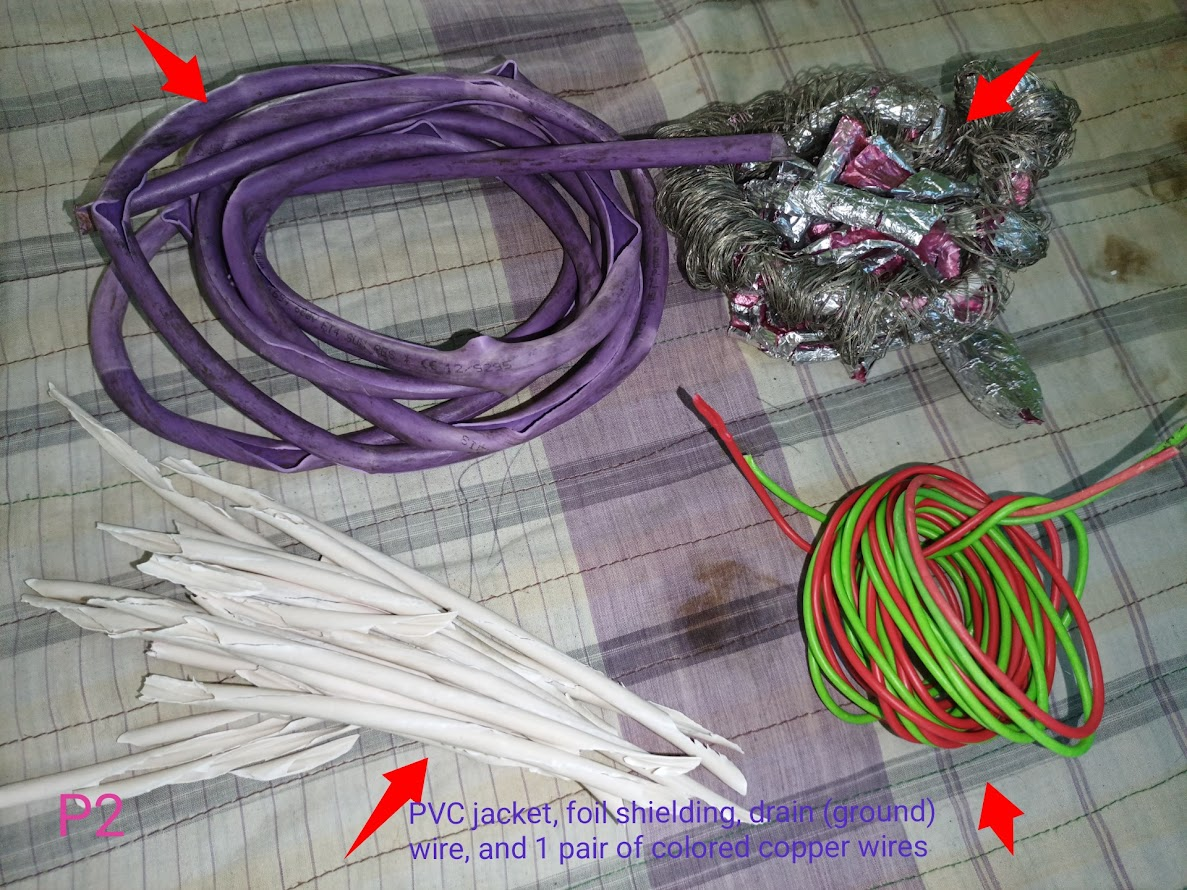
This cable is made of everything: the outermost is the PVC jacket, then the foil shielding, then the drain (ground) wire, and finally the innermost 1 pair of twisted coloured copper wires. I step by step open the cable and take out the inner copper wires and make them usable as customised jumper wires — so that the circuit on the breadboard is very tidy and also convenient for practical work. Now I show the next steps.
Step -01
First I took the wires in my hand. And to explain to you, I took male-to-male jumper wires bought from the market.
Step -02
Then the main thing of this work is the breadboard, and to explain to you, I took it. Now you can see that I have connected some electronic parts and some jumper wires on the breadboard which look random.
Step -03
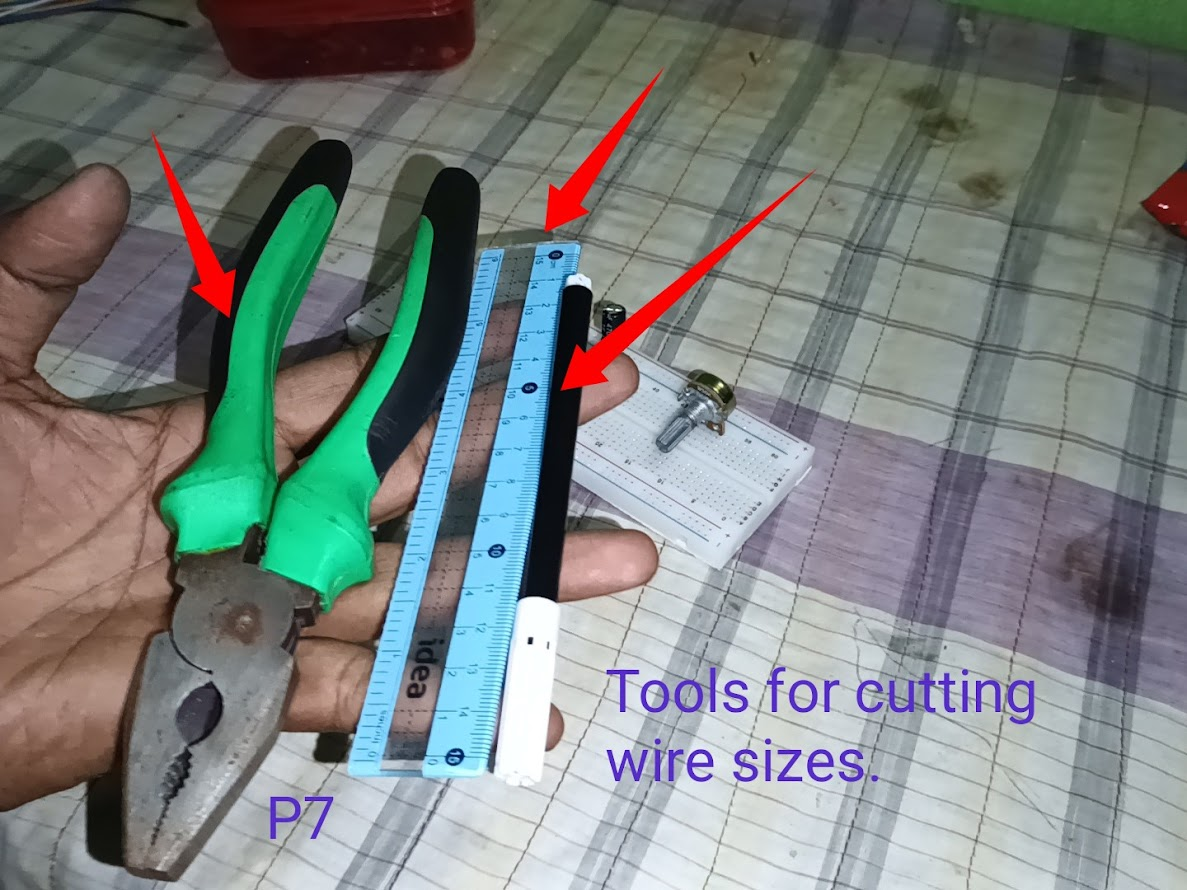
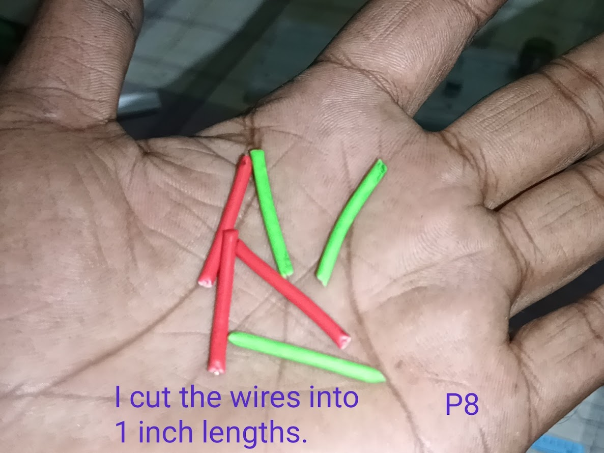
Now I will show you by making jumper wires in my own way, so I took some tools. Then I cut the wires by an inch; you can cut them in different amounts if you want.
Step -04
Then I cut the plastic on the copper with a blade and took out the copper from inside as per the measurement. I bent the copper to make it look very beautiful on the breadboard.
Step -05
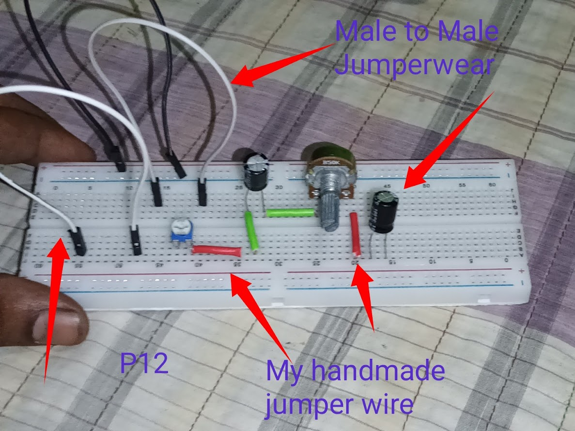
Then you can see that I have placed some parts on the breadboard and jumpered the connections to explain to you. And in the next picture, you can see that on one side I have connected the long wires from male to male, and they look two ways.
Step -06
You saw in the previous picture that connecting with long wires creates a problem. So you can cut the wires according to your size in this way. Then I have placed the example parts here to explain and connected them nicely, put the jumpers and completed the circuit. According to the diagram, you can place the parts here and connect the jumpers and start any project with the power line; there is no problem.
Video Tutorial: To better understand the practical part of this tutorial, you can watch the video below.
🟩 Thank you for reading my post and giving your valuable time. Stay well and stay healthy. God bless you.
🟩
.png)


.gif)
